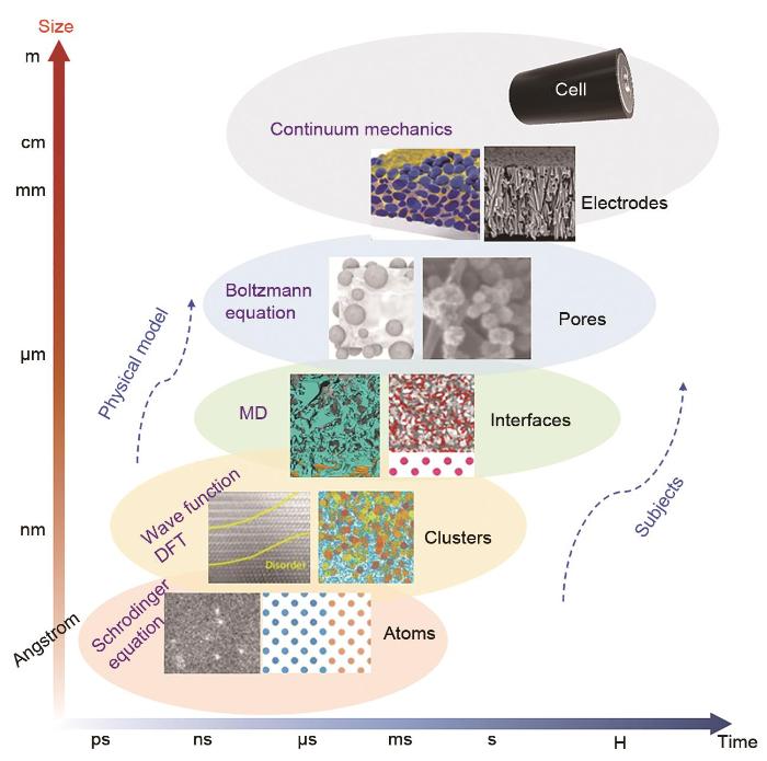
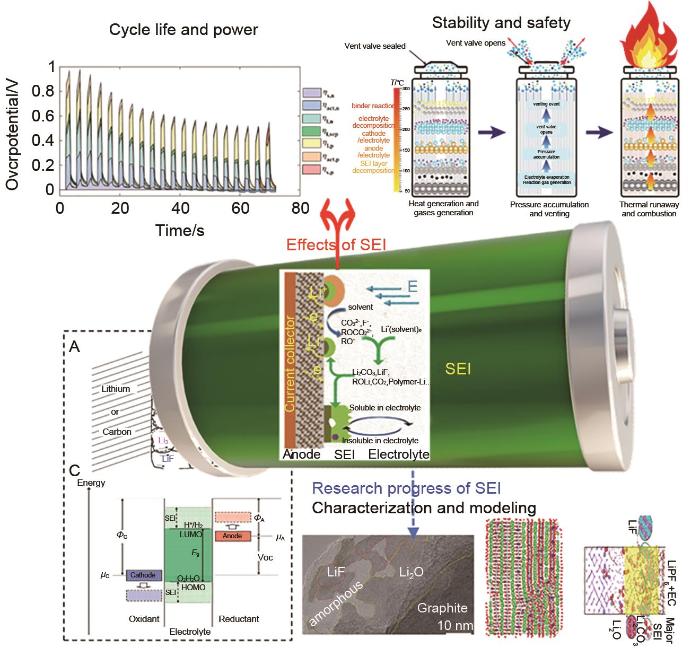
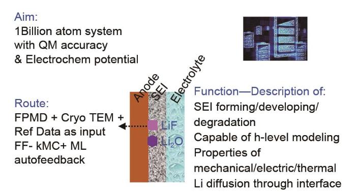
The solid-electrolyte interface (SEI) on the highly reductive negative electrode surface of lithium-ion batteries is a key component affecting the electrical performance and stability; however, the formation of SEI involves complex processes in multiscale and multiphysical fields with extremely complex components. In the "black box" environment of a battery shell, the existing technology cannot characterize SEI, and in situ technology is difficult to obtain highly precise results. Using mathematical methods to model SEI is expected to decouple the complex physical fields and accurately describe the mechanisms and processes of SEI formation and evolution, which is a research hotspot in the field of battery. In this study, first, we describe the main methods and progress of SEI modeling from the atomic scale to mesoscale, including first-principles classical molecular dynamics, reactive molecular dynamics, classical molecular dynamics, Monte Carlo simulations, and macroscopic models. We also summarize some modeling applications in guiding electrode material synthesis and electrolyte modification, focusing on the difficulties and shortcomings of multiscale modeling. Next, we propose a force field algorithm platform based on the electrochemical potential field characteristics of SEI, expanding the modeling to tens of thousands or even hundreds of millions of atoms using the kinetic Monte Carlo simulations and machine learning assistance. Then, calculations are performed step by step, combining experimental verification and expert evaluation to promote convergence. Finally, we obtain an SEI model with quantum mechanical accuracy and electrochemical potential field, which is expected to realize SEI modeling at various lengths and timescales.
Keywords:lithium-ion batteries
;
multiscale modeling
;
molecular dynamics simulation
;
reaction force field
;
solid electrolyte interface
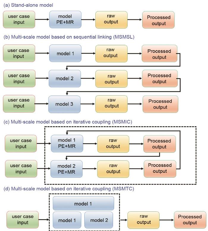
MSM与独立模型[图3(a)]有本质上的不同,独立模型的输入由用户提供,而输出不被任何其他模型使用。MSM根据内部不同尺度结果间的关系可分为三类。①基于顺序链接的多尺度模型(MSMSL):这些模型具有两个或多个模型方程的顺序解,其中一个模型的结果输出[12]被用作下一个模型的输入(单向依赖)[图3(b)]。其典型的例子是在电子结构计算的基础上,利用经典原子力场(FF)进行MD仿真。②基于交互迭代耦合的多尺度模型(multiscale model based on iterative coupling,MSMIC):这些模型依赖于两个或多个模型(各自有适用空间尺度)方程的迭代解。对于两个空间不同尺度,第一个模型的结果可被用作第二个模型的输入,反之亦然。每个模型都有自己的输出结果,这些结果交互耦合带来一个闭环的数据流[图3(c)],而通常需要多次迭代才能使得数值解最终达到收敛。此方面典型例子是使用kMC模型来解析界面上的化学反应动力学,该化学反应动力学由描述这些化学物质沿多孔电极输运的模型来解析(反应动力学作为描述输运的空间微分方程的汇/源项)。③基于紧耦合(MSMTC)的多尺度模型:这些模型由两个或多个更偏物理的模型(每个模型都聚焦在单一空间尺度上)方程的并行解组成,其中每个模型的物理和材料方面的参数被归纳为单系统求解[图3(d)]。模型的相互依赖性通过在多个方程中通用的物理量来表示,且所有模型只有一个输出。此方面典型的例子是在锂离子电池内部多孔电极研究方面,使用温度相关参数的连续介质模型描述电化学反应和输运机制。
Fig. 3
Workflows of (a) stand-alone models; (b) multiscale models based on sequential linking (MSMSL); (c) multiscale models based on iterative coupling (MSMIC); and (d) multiscale models based on tight coupling (MSMTC). “PE” refers to “physical equation” (mathematical equation based on a fundamental physics theory which defines the relations between physics quantities of an entity) and “MR” to material relation (materials specific equation providing a value for a parameter in the physics equation)[13]
MSM的控制方程通常是非线性的、耦合的偏微分方程,需要在一维、二维和三维空间上进行时间和空间的求解。用于研究电池材料的MSM方法包括从头计算分子动力学方法(ab initio Molecular Dynamics,MSMIC)、ReaxFF方法(MSMSL)和COSMO方法(MSMSL)。典型软件包括Gaussian[14]、GAMESS[15]、SIESTA[16]和COSMO-RS[17]等,这些软件已被广泛应用在电池不同尺度对象的模拟研究中。MSMIC和MSMTC方法已经在Matlab[18]、Fluent[19]、COMSOL[20-21]及这些软件的组合中应用。一些商业软件将以上方法或软件平台进行组合,为锂离子电池模拟提供综合解决方案,例如CD-adapco公司的STAR-CCM+[22]及其电池模拟和设计模块等。
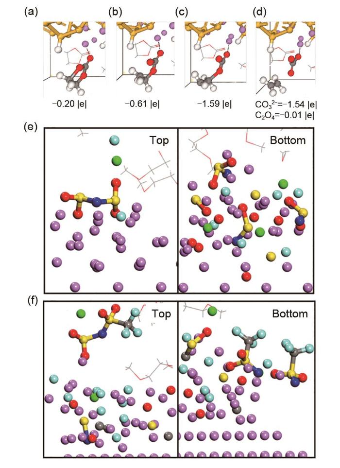
AIMD模拟也被应用于研究硅基电极上的EC还原,硅不同程度的锂化对SEI的还原机理(如EC的分解,以及SEI的不同组成和物理性质等)产生了显著的影响。即使在硅电极锂化的初期阶段(LiSi4,LiSi2),EC的还原也是可能发生的,这是由吸附过程中C—Si键的形成引发的EC两电子同时还原[图4(a)~(d)]。Li x Si y 合金的反应性较强的表面会发生两种双电子机制还原EC:被吸附在电极上的溶剂分子的两个电子同时还原,而靠近界面分子的两个电子依次还原。深度锂化相Li13Si4的表面非常活跃,并通过四电子机制还原EC。总地来说,Si电极的反应活性与晶面和原子距离等晶体特性有关[43],其与石墨电极活性受表面官能团影响形成鲜明对比。模拟结果表明,EC与表面锂原子相互作用至关重要:电极表面原子间距离过短会阻碍Li-EC相互作用,甚至阻碍Li-EC的还原过程。Moradabadi等[44]研究了一系列Sn和Li基电极的界面,EC在锂化的锡表面也会分解。与金属锂表面相比(-2.4 eV),在覆Li锡和锂锡合金表面通过双电子机制还原EC生成CO32-更为容易(分别为1.90 eV和1.84 eV)。
Fig. 4
Decomposition of EC. Initially one electron is transferred from the surface to (a) Li-EC, causing a (b) Ccarbonyl —Oring bond to break. Subsequently, a second electron is transferred to (c) the EC- radical anion, triggering the breaking of a second Ccarbonyl —Oring bond and (d) generating the C2H4+CO32-pair. The net charges of the EC molecule and the CO32-/ C2H4 products are shown[43]. SEI after 16 ps of simulation using 4 mol/L (e) LiFSI or (f) LiTFSI in DME electrolytes vs. a lithium surface[49]
Fig. 5
(a) Energy profile for breaking C2H4 from o-EC/Li+, as obtained from QC calculations and gas phase simulations using ReaxFF at 10 K[63]; (b) Schematic of a Li metal electrode dipped in an electrolyte (left) and initial configuration of the cell (right)[64]; (c) Distribution of the SEI components for different electrolytes (left). Atomic configurations from MD simulations; the components of the SEI are identified (right)[64]; (d) Potential energy profile for the reduction of EC/Li+ and the radical termination reactions according to various pathways. ΔER and ΔEB denote the reaction energy and reaction barrier, respectively. Color scheme: cyan, carbon; white, hydrogen; red, oxygen; purple, Li+; large blue sphere, electron[70]
图6
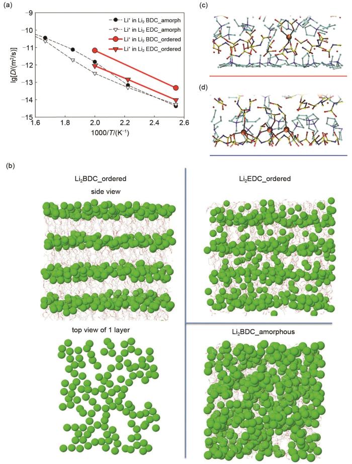
(a) 由Li2BDC和Li2EDC组成的有序和非晶SEI模型的Li+ 阳离子扩散系数[54];(b)在393 K处,Li2BDC和Li2EDC有序分布和Li2BDC无定形分布的Li+ 的计算模拟图;在(c)负极电位和(d)正极电位的双层中具有代表性的Li+-阴离子配位,红色和蓝色条分别表示阳极和阴极表面的( x, y )平面[76]
Fig. 6
(a) Li+ cation diffusion coefficients for ordered and amorphous SEI models consisting of Li2BDC and Li2EDC[54]; (b) Snapshots highlighting the Li+ distribution in ordered Li2BDC and Li2EDC, and amorphous Li2BDC, all at 393 K; Representative Li+-anion coordination in the double layer at (c) negative electrode potentials and (d) positive electrode potentials. Red and blue bars indicate the (x, y) plane of the anode and cathode surfaces, respectively[76]
Fig. 7
(a) Model system and reaction scheme (cyan, carbon; red, oxygen; white, hydrogen; orange, phosphorus; green, fluorine; blue, lithium) [77]. (b) Schematic representation of the 4 types of events selected to occur in the kMC simulations[79]. (c, d) Effect of SEI solvent activation energy on the total charging time and SEI thickness during a full charging process [80]
FRANCO A A, RUCCI A, BRANDELL D, et al. Boosting rechargeable batteries R&D by multiscale modeling: Myth or reality?[J]. Chemical Reviews, 2019, 119(7): 4569-4627.
CHENG X B, ZHANG R, ZHAO C Z, et al. A review of solid electrolyte interphases on lithium metal anode[J]. Advanced Science (Weinheim, Baden-Wurttemberg, Germany), 2015, 3(3): doi: 10.1002/advs.201500213.
PINSON M B, BAZANT M Z. Theory of SEI formation in rechargeable batteries: Capacity fade, accelerated aging and lifetime prediction[J]. Journal of the Electrochemical Society, 2012, 160(2): A243-A250.
WU H P, JIA H, WANG C M, et al. Recent progress in understanding solid electrolyte interphase on lithium metal anodes[J]. Advanced Energy Materials, 2021, 11(5): doi: 10.1002/aenm.202003092.
SUO L M, OH D, LIN Y X, et al. How solid-electrolyte interphase forms in aqueous electrolytes[J]. Journal of the American Chemical Society, 2017, 139(51): 18670-18680.
LI Y Z, LI Y B, PEI A, et al. Atomic structure of sensitive battery materials and interfaces revealed by cryo-electron microscopy[J]. Science, 2017, 358(6362): 506-510.
AURBACH D, EIN-ELY Y, ZABAN A. The surface chemistry of lithium electrodes in alkyl carbonate solutions[J]. Journal of the Electrochemical Society, 1994, 141(1): L1-L3.
PELED E, GOLODNITSKY D, ARDEL G. Advanced model for solid electrolyte interphase electrodes in liquid and polymer electrolytes[J]. Journal of the Electrochemical Society, 1997, 144(8): L208-L210.
XU Y B, WU H P, HE Y, et al. Atomic to nanoscale origin of vinylene carbonate enhanced cycling stability of lithium metal anode revealed by cryo-transmission electron microscopy[J]. Nano Letters, 2020, 20(1): 418-425.
CARCÍA A, PAPIOR N, AKHTAR A, et al. Siesta: Recent developments and applications[J]. The Journal of Chemical Physics, 2020, 152: doi: 10.1016/j.jma.2020.06.021.
CAI L, WHITE R E. Mathematical modeling of a lithium ion battery with thermal effects in COMSOL Inc. Multiphysics (MP) software[J]. Journal of Power Sources, 2011, 196(14): 5985-5989.
KRESSE G, FURTHMÜLLER J. Efficient iterative schemes for ab initio total-energy calculations using a plane-wave basis set[J]. Physical Review B, Condensed Matter, 1996, 54(16): 11169-11186.
BLAHA P, SCHWARZ K, MADSEN G K H, et al. WIEN2k, an augmented plane wave plus local orbitals program for calculating crystal properties [R/OL]. Vienna University of Technology. 2001[2022-08-01]. https://www.researchgate.net/publication/237132866.
RATCLIFF L E, GRISANTI L, GENOVESE L, et al. Toward fast and accurate evaluation of charge on-site energies and transfer integrals in supramolecular architectures using linear constrained density functional theory (CDFT)-based methods[J]. Journal of Chemical Theory and Computation, 2015, 11(5): 2077-2086.
VALIEV M, BYLASKA E J, GOVIND N, et al. NWChem: A comprehensive and scalable open-source solution for large scale molecular simulations[J]. Computer Physics Communications, 2010, 181(9): 1477-1489.
PÁLL S, ZHMUROV A, BAUER P, et al. Heterogeneous parallelization and acceleration of molecular dynamics simulations in GROMACS[J]. Journal Of Chemical Physics, 2020, 153: doi: 10.1063/5.0018516.
THOMPSON A P, AKTULGA H M, BERGER R, et al. LAMMPS-a flexible simulation tool for particle-based materials modeling at the atomic, meso, and continuum scales[J]. Computer Physics Communications, 2022, 271: doi: 10.1016/j.cpc.2021.108171.
CASE D A, CHEATHAM T E, DARDEN III T, et al. The Amber biomolecular simulation programs[J]. Journal of Computational Chemistry, 2005, 26(16): 1668-1688.
UHRIN M, HUBER S P, YU J, et al. Workflows in AiiDA: Engineering a high-throughput, event-based engine for robust and modular computational workflows[J]. Computational Materials Science, 2021, 187: doi: 10.1016/j.commatsci.2020.110086.
GANESH P, KENT P R C, JIANG D E. Solid-electrolyte interphase formation and electrolyte reduction at Li-ion battery graphite anodes: Insights from first-principles molecular dynamics[J]. The Journal of Physical Chemistry C, 2012, 116(46): 24476-24481.
LEUNG K, BUDZIEN J L. Ab initio molecular dynamics simulations of the initial stages of solid-electrolyte interphase formation on lithium ion battery graphitic anodes[J]. Physical Chemistry Chemical Physics: PCCP, 2010, 12(25): 6583-6586.
BRENNAN M D, BREEDON M, BEST A S, et al. Surface reactions of ethylene carbonate and propylene carbonate on the Li(001) surface[J]. Electrochimica Acta, 2017, 243: 320-330.
YU J M, BALBUENA P B, BUDZIEN J, et al. Hybrid DFT functional-based static and molecular dynamics studies of excess electron in liquid ethylene carbonate[J]. Journal of the Electrochemical Society, 2011, 158(4): A400.
MARTINEZ DE LA HOZ J M, LEUNG K, BALBUENA P B. Reduction mechanisms of ethylene carbonate on si anodes of lithium-ion batteries: Effects of degree of lithiation and nature of exposed surface[J]. ACS Applied Materials & Interfaces, 2013, 5(24): 13457-13465.
MORADABADI A, BAKHTIARI M, KAGHAZCHI P. Effect of anode composition on solid electrolyte interphase formation[J]. Electrochimica Acta, 2016, 213: 8-13.
LEUNG K, QI Y, ZAVADIL K R, et al. Using atomic layer deposition to hinder solvent decomposition in lithium ion batteries: First-principles modeling and experimental studies[J]. Journal of the American Chemical Society, 2011, 133(37): 14741-14754.
CHEN X, HOU T Z, LI B, et al. Towards stable lithium-sulfur batteries: Mechanistic insights into electrolyte decomposition on lithium metal anode[J]. Energy Storage Materials, 2017, 8: 194-201.
CAMACHO-FORERO L E, SMITH T W, BERTOLINI S, et al. Reactivity at the lithium-metal anode surface of lithium-sulfur batteries[J]. The Journal of Physical Chemistry C, 2015, 119(48): 26828-26839.
YILDIRIM H, HASKINS J B, BAUSCHLICHER C W Jr, et al. Decomposition of ionic liquids at lithium interfaces. 1. Ab initio molecular dynamics simulations[J]. The Journal of Physical Chemistry C, 2017, 121(51): 28214-28234.
CAMACHO-FORERO L E, SMITH T W, BALBUENA P B. Effects of high and low salt concentration in electrolytes at lithium-metal anode surfaces[J]. The Journal of Physical Chemistry C, 2017, 121(1): 182-194.
SODEYAMA K, YAMADA Y, AIKAWA K, et al. Sacrificial anion reduction mechanism for electrochemical stability improvement in highly concentrated Li-salt electrolyte[J]. The Journal of Physical Chemistry C, 2014, 118(26): 14091-14097.
LEUNG K, JUNGJOHANN K L. Spatial heterogeneities and onset of passivation breakdown at lithium anode interfaces[J]. The Journal of Physical Chemistry C, 2017, 121(37): 20188-20196.
BENITEZ L, SEMINARIO J M. Electron transport and electrolyte reduction in the solid-electrolyte interphase of rechargeable lithium ion batteries with silicon anodes[J]. The Journal of Physical Chemistry C, 2016, 120(32): 17978-17988.
BEDROV D, BORODIN O, HOOPER J B. Li+ transport and mechanical properties of model solid electrolyte interphases (SEI): Insight from atomistic molecular dynamics simulations[J]. The Journal of Physical Chemistry C, 2017, 121(30): 16098-16109.
SHIN H, PARK J, HAN S, et al. Component-/structure-dependent elasticity of solid electrolyte interphase layer in Li-ion batteries: Experimental and computational studies. Journal of Power Sources, 2015, 277: 169-179.
LIU Z, QI Y, LIN Y X, et al. Interfacial study on solid electrolyte interphase at Li metal anode: Implication for Li dendrite growth[J]. Journal of the Electrochemical Society, 2016, 163(3): A592-A598.
SOTO F A, MA Y G, MARTINEZ DE LA HOZ J M, et al. Formation and growth mechanisms of solid-electrolyte interphase layers in rechargeable batteries[J]. Chemistry of Materials, 2015, 27(23): 7990-8000.
PAN J, ZHANG Q L, XIAO X C, et al. Design of nanostructured heterogeneous solid ionic coatings through a multiscale defect model[J]. ACS Applied Materials & Interfaces, 2016, 8(8): 5687-5693.
SHI S Q, LU P, LIU Z Y, et al. Direct calculation of Li-ion transport in the solid electrolyte interphase[J]. Journal of the American Chemical Society, 2012, 134(37): 15476-15487.
OKUNO Y, USHIROGATA K, SODEYAMA K, et al. Decomposition of the fluoroethylene carbonate additive and the glue effect of lithium fluoride products for the solid electrolyte interphase: An ab initio study[J]. Physical Chemistry Chemical Physics: PCCP, 2016, 18(12): 8643-8653.
LEUNG K. First-principles modeling of Mn(II) migration above and dissolution from LixMn2O4 (001) surfaces[J]. Chemistry of Materials, 2017, 29(6): 2550-2562.
BEDROV D, SMITH G D, VAN DUIN A C T. Reactions of singly-reduced ethylene carbonate in lithium battery electrolytes: A molecular dynamics simulation study using the ReaxFF[J]. The Journal of Physical Chemistry A, 2012, 116(11): 2978-2985.
KIM S P, VAN DUIN A C T, SHENOY V B. Effect of electrolytes on the structure and evolution of the solid electrolyte interphase (SEI) in Li-ion batteries: A molecular dynamics study[J]. Journal of Power Sources, 2011, 196(20): 8590-8597.
PEREIRA-NABAIS C, ŚWIATOWSKA J, CHAGNES A, et al. Interphase chemistry of Si electrodes used as anodes in Li-ion batteries[J]. Applied Surface Science, 2013, 266: 5-16.
EDSTRÖM K, HERSTEDT M, ABRAHAM D P. A new look at the solid electrolyte interphase on graphite anodes in Li-ion batteries[J]. Journal of Power Sources, 2006, 153(2): 380-384.
PELED E, BAR TOW D, MERSON A, et al. Composition, depth profiles and lateral distribution of materials in the SEI built on HOPG-TOF SIMS and XPS studies[J]. Journal of Power Sources, 2001, 97/98: 52-57.
LU M, CHENG H, YANG Y. A comparison of solid electrolyte interphase (SEI) on the artificial graphite anode of the aged and cycled commercial lithium ion cells[J]. Electrochimica Acta, 2008, 53(9): 3539-3546.
YUN K S, PAI S J, YEO B C, et al. Simulation protocol for prediction of a solid-electrolyte interphase on the silicon-based anodes of a lithium-ion battery: ReaxFF reactive force field[J]. The Journal of Physical Chemistry Letters, 2017, 8(13): 2812-2818.
ISLAM M M, KOLESOV G, VERSTRAELEN T, et al. eReaxFF: A pseudoclassical treatment of explicit electrons within reactive force field simulations[J]. Journal of Chemical Theory and Computation, 2016, 12(8): 3463-3472.
CHENG T, MERINOV B V, MOROZOV S, et al. Quantum mechanics reactive dynamics study of solid Li-electrode/Li6PS5Cl-electrolyte interface[J]. ACS Energy Letters, 2017, 2(6): 1454-1459.
BORODIN O, ZHUANG G V, ROSS P N, et al. Molecular dynamics simulations and experimental study of lithium ion transport in dilithium ethylene dicarbonate[J]. The Journal of Physical Chemistry C, 2013, 117(15): 7433-7444.
BORODIN O, BEDROV D. Interfacial structure and dynamics of the lithium alkyl dicarbonate SEI components in contact with the lithium battery electrolyte[J]. The Journal of Physical Chemistry C, 2014, 118(32): 18362-18371.
JEONG S K, INABA M, IRIYAMA Y, et al. AFM study of surface film formation on a composite graphite electrode in lithium-ion batteries[J]. Journal of Power Sources, 2003, 119/120/121: 555-560.
JORN R, KUMAR R, ABRAHAM D P, et al. Atomistic modeling of the electrode-electrolyte interface in Li-ion energy storage systems: Electrolyte structuring[J]. The Journal of Physical Chemistry C, 2013, 117(8): 3747-3761.
HASKINS J B, WU J J, LAWSON J W. Computational and experimental study of Li-doped ionic liquids at electrified interfaces[J]. The Journal of Physical Chemistry C, Nanomaterials and Interfaces, 2016, 120(22): 11993-12011.
TAKENAKA N, SUZUKI Y, SAKAI H, et al. On electrolyte-dependent formation of solid electrolyte interphase film in lithium-ion batteries: Strong sensitivity to small structural difference of electrolyte molecules[J]. The Journal of Physical Chemistry C, 2014, 118(20): 10874-10882.
TAKENAKA N, SAKAI H, SUZUKI Y, et al. A computational chemical insight into microscopic additive effect on solid electrolyte interphase film formation in sodium-ion batteries: Suppression of unstable film growth by intact fluoroethylene carbonate[J]. The Journal of Physical Chemistry C, 2015, 119(32): 18046-18055.
METHEKAR R N, NORTHROP P W C, CHEN K J, et al. Kinetic Monte Carlo simulation of surface heterogeneity in graphite anodes for lithium-ion batteries: Passive layer formation[C]//Proceedings of the 2011 American Control Conference. June 29-July 1, 2011, San Francisco, CA, USA. IEEE, 2011: 1512-1517.
HAO F, LIU Z X, BALBUENA P B, et al. Mesoscale elucidation of solid electrolyte interphase layer formation in Li-ion battery anode[J]. The Journal of Physical Chemistry C, 2017, 121(47): 26233-26240.
RÖDER F, BRAATZ R D, KREWER U. Multi-scale simulation of heterogeneous surface film growth mechanisms in lithium-ion batteries[J]. Journal of the Electrochemical Society, 2017, 164(11): E3335-E3344.
SHINAGAWA C, USHIYAMA H, YAMASHITA K. Multiscale simulations for lithium-ion batteries: SEI film growth and capacity fading[J]. Journal of the Electrochemical Society, 2017, 164(13): A3018-A3024.
CHRISTENSEN J, NEWMAN J. A mathematical model for the lithium-ion negative electrode solid electrolyte interphase[J]. Journal of the Electrochemical Society, 2004, 151(11): A1977.
COLCLASURE A M, SMITH K A, KEE R J. Modeling detailed chemistry and transport for solid-electrolyte-interface (SEI) films in Li-ion batteries[J]. Electrochimica Acta, 2011, 58: 33-43.
SAFARI M, MORCRETTE M, TEYSSOT A, et al. Multimodal physics-based aging model for life prediction of Li-ion batteries[J]. Journal of the Electrochemical Society, 2009, 156(3): A145.
LAWDER M T, NORTHROP P W C, SUBRAMANIAN V R. Model-based SEI layer growth and capacity fade analysis for EV and PHEV batteries and drive cycles[J]. Journal of the Electrochemical Society, 2014, 161(14): A2099-A2108.
... MSM与独立模型[图3(a)]有本质上的不同,独立模型的输入由用户提供,而输出不被任何其他模型使用.MSM根据内部不同尺度结果间的关系可分为三类.①基于顺序链接的多尺度模型(MSMSL):这些模型具有两个或多个模型方程的顺序解,其中一个模型的结果输出[12]被用作下一个模型的输入(单向依赖)[图3(b)].其典型的例子是在电子结构计算的基础上,利用经典原子力场(FF)进行MD仿真.②基于交互迭代耦合的多尺度模型(multiscale model based on iterative coupling,MSMIC):这些模型依赖于两个或多个模型(各自有适用空间尺度)方程的迭代解.对于两个空间不同尺度,第一个模型的结果可被用作第二个模型的输入,反之亦然.每个模型都有自己的输出结果,这些结果交互耦合带来一个闭环的数据流[图3(c)],而通常需要多次迭代才能使得数值解最终达到收敛.此方面典型例子是使用kMC模型来解析界面上的化学反应动力学,该化学反应动力学由描述这些化学物质沿多孔电极输运的模型来解析(反应动力学作为描述输运的空间微分方程的汇/源项).③基于紧耦合(MSMTC)的多尺度模型:这些模型由两个或多个更偏物理的模型(每个模型都聚焦在单一空间尺度上)方程的并行解组成,其中每个模型的物理和材料方面的参数被归纳为单系统求解[图3(d)].模型的相互依赖性通过在多个方程中通用的物理量来表示,且所有模型只有一个输出.此方面典型的例子是在锂离子电池内部多孔电极研究方面,使用温度相关参数的连续介质模型描述电化学反应和输运机制. ...
2
... MSM与独立模型[图3(a)]有本质上的不同,独立模型的输入由用户提供,而输出不被任何其他模型使用.MSM根据内部不同尺度结果间的关系可分为三类.①基于顺序链接的多尺度模型(MSMSL):这些模型具有两个或多个模型方程的顺序解,其中一个模型的结果输出[12]被用作下一个模型的输入(单向依赖)[图3(b)].其典型的例子是在电子结构计算的基础上,利用经典原子力场(FF)进行MD仿真.②基于交互迭代耦合的多尺度模型(multiscale model based on iterative coupling,MSMIC):这些模型依赖于两个或多个模型(各自有适用空间尺度)方程的迭代解.对于两个空间不同尺度,第一个模型的结果可被用作第二个模型的输入,反之亦然.每个模型都有自己的输出结果,这些结果交互耦合带来一个闭环的数据流[图3(c)],而通常需要多次迭代才能使得数值解最终达到收敛.此方面典型例子是使用kMC模型来解析界面上的化学反应动力学,该化学反应动力学由描述这些化学物质沿多孔电极输运的模型来解析(反应动力学作为描述输运的空间微分方程的汇/源项).③基于紧耦合(MSMTC)的多尺度模型:这些模型由两个或多个更偏物理的模型(每个模型都聚焦在单一空间尺度上)方程的并行解组成,其中每个模型的物理和材料方面的参数被归纳为单系统求解[图3(d)].模型的相互依赖性通过在多个方程中通用的物理量来表示,且所有模型只有一个输出.此方面典型的例子是在锂离子电池内部多孔电极研究方面,使用温度相关参数的连续介质模型描述电化学反应和输运机制.
<strong>Workflows of (a) stand-alone models; (b) multiscale models based on sequential linking (MSMSL); (c) multiscale models based on iterative coupling (MSMIC); and (d) multiscale models based on tight coupling (MSMTC).</strong> “<strong>PE</strong>” <strong>refers to</strong> “<strong>physical equation</strong>” <strong>(mathematical equation based on a fundamental physics theory which defines the relations between physics quantities of an entity) and</strong> “<strong>MR</strong>” <strong>to material relation (materials specific equation providing a value for a parameter in the physics equation)</strong><sup>[<xref ref-type="bibr" rid="R13">13</xref>]</sup>Fig. 3
MSM的控制方程通常是非线性的、耦合的偏微分方程,需要在一维、二维和三维空间上进行时间和空间的求解.用于研究电池材料的MSM方法包括从头计算分子动力学方法(ab initio Molecular Dynamics,MSMIC)、ReaxFF方法(MSMSL)和COSMO方法(MSMSL).典型软件包括Gaussian[14]、GAMESS[15]、SIESTA[16]和COSMO-RS[17]等,这些软件已被广泛应用在电池不同尺度对象的模拟研究中.MSMIC和MSMTC方法已经在Matlab[18]、Fluent[19]、COMSOL[20-21]及这些软件的组合中应用.一些商业软件将以上方法或软件平台进行组合,为锂离子电池模拟提供综合解决方案,例如CD-adapco公司的STAR-CCM+[22]及其电池模拟和设计模块等. ...
... [13]Fig. 3
MSM的控制方程通常是非线性的、耦合的偏微分方程,需要在一维、二维和三维空间上进行时间和空间的求解.用于研究电池材料的MSM方法包括从头计算分子动力学方法(ab initio Molecular Dynamics,MSMIC)、ReaxFF方法(MSMSL)和COSMO方法(MSMSL).典型软件包括Gaussian[14]、GAMESS[15]、SIESTA[16]和COSMO-RS[17]等,这些软件已被广泛应用在电池不同尺度对象的模拟研究中.MSMIC和MSMTC方法已经在Matlab[18]、Fluent[19]、COMSOL[20-21]及这些软件的组合中应用.一些商业软件将以上方法或软件平台进行组合,为锂离子电池模拟提供综合解决方案,例如CD-adapco公司的STAR-CCM+[22]及其电池模拟和设计模块等. ...
2
... MSM的控制方程通常是非线性的、耦合的偏微分方程,需要在一维、二维和三维空间上进行时间和空间的求解.用于研究电池材料的MSM方法包括从头计算分子动力学方法(ab initio Molecular Dynamics,MSMIC)、ReaxFF方法(MSMSL)和COSMO方法(MSMSL).典型软件包括Gaussian[14]、GAMESS[15]、SIESTA[16]和COSMO-RS[17]等,这些软件已被广泛应用在电池不同尺度对象的模拟研究中.MSMIC和MSMTC方法已经在Matlab[18]、Fluent[19]、COMSOL[20-21]及这些软件的组合中应用.一些商业软件将以上方法或软件平台进行组合,为锂离子电池模拟提供综合解决方案,例如CD-adapco公司的STAR-CCM+[22]及其电池模拟和设计模块等. ...
... AIMD已被广泛应用到EC中不同类型键的断裂竞争机制上[40,42,45].Yu等[42]使用简化的方法模拟了EC在金属锂和石墨表面的分解,结果表明前者速度更快些.应用此方法可很好地模拟碳酸酯上C=O的断键.此外,Yu等[42]的方法还可模拟在没有任何电极的情况下电解质液相中有一个电子和两个电子过剩的情况,结果表明多余的电子主要离域到两个EC分子上,而不是与Li+共轭.此外,—EC的键解离势垒比EC—Li+配合物的键离解势垒低,导致前者更易分解,而Li+的存在则大大稳定了EC.第二个电子通常攻击—EC,通过经典的双电子机制引起断键.Leung等[45]针对Li|EC|Li的典型单元,在两个6原子厚度的Li金属箔之间模拟了32个EC分子的分解情况,结果表明12个分解分子中有11个通过碳羰基氧环键裂解,只有1个通过碳环氧环键裂解.这个结果表明,因为这两种反应都有极低的能量势垒,而后者的产物CO32-在热力学上非常稳定,其原因可能是锂表面EC分子的几何弯曲更易于分解造成的.Brennan等[41]使用AIMD模拟来确定EC和PC(丙烯碳酸酯)在锂金属电极上的首选吸附位点和取向,其使用了一个由7片Li晶体层组成的模型,发现有三种取向:①EC方向由两个氧原子连接两个锂原子;②EC通过一个羰基氧连接两个锂原子;③EC通过一个羰基氧连接到一个锂原子.EC和PC都发生了此现象.①情况最稳定,因此被研究的更详细.在①中,EC首先接受电极上的一个电子,然后破坏C羰基O环键,接着从Li表面转移另一个电子,并破坏第二个C羰基O环键.PC的分解过程也非常相似,但要慢得多;由于甲基的存在可引起更高的键解离势垒,因此EC可在7 ps内分解,而PC则需要超过20 ps. ...
... AIMD已被广泛应用到EC中不同类型键的断裂竞争机制上[40,42,45].Yu等[42]使用简化的方法模拟了EC在金属锂和石墨表面的分解,结果表明前者速度更快些.应用此方法可很好地模拟碳酸酯上C=O的断键.此外,Yu等[42]的方法还可模拟在没有任何电极的情况下电解质液相中有一个电子和两个电子过剩的情况,结果表明多余的电子主要离域到两个EC分子上,而不是与Li+共轭.此外,—EC的键解离势垒比EC—Li+配合物的键离解势垒低,导致前者更易分解,而Li+的存在则大大稳定了EC.第二个电子通常攻击—EC,通过经典的双电子机制引起断键.Leung等[45]针对Li|EC|Li的典型单元,在两个6原子厚度的Li金属箔之间模拟了32个EC分子的分解情况,结果表明12个分解分子中有11个通过碳羰基氧环键裂解,只有1个通过碳环氧环键裂解.这个结果表明,因为这两种反应都有极低的能量势垒,而后者的产物CO32-在热力学上非常稳定,其原因可能是锂表面EC分子的几何弯曲更易于分解造成的.Brennan等[41]使用AIMD模拟来确定EC和PC(丙烯碳酸酯)在锂金属电极上的首选吸附位点和取向,其使用了一个由7片Li晶体层组成的模型,发现有三种取向:①EC方向由两个氧原子连接两个锂原子;②EC通过一个羰基氧连接两个锂原子;③EC通过一个羰基氧连接到一个锂原子.EC和PC都发生了此现象.①情况最稳定,因此被研究的更详细.在①中,EC首先接受电极上的一个电子,然后破坏C羰基O环键,接着从Li表面转移另一个电子,并破坏第二个C羰基O环键.PC的分解过程也非常相似,但要慢得多;由于甲基的存在可引起更高的键解离势垒,因此EC可在7 ps内分解,而PC则需要超过20 ps. ...
... AIMD已被广泛应用到EC中不同类型键的断裂竞争机制上[40,42,45].Yu等[42]使用简化的方法模拟了EC在金属锂和石墨表面的分解,结果表明前者速度更快些.应用此方法可很好地模拟碳酸酯上C=O的断键.此外,Yu等[42]的方法还可模拟在没有任何电极的情况下电解质液相中有一个电子和两个电子过剩的情况,结果表明多余的电子主要离域到两个EC分子上,而不是与Li+共轭.此外,—EC的键解离势垒比EC—Li+配合物的键离解势垒低,导致前者更易分解,而Li+的存在则大大稳定了EC.第二个电子通常攻击—EC,通过经典的双电子机制引起断键.Leung等[45]针对Li|EC|Li的典型单元,在两个6原子厚度的Li金属箔之间模拟了32个EC分子的分解情况,结果表明12个分解分子中有11个通过碳羰基氧环键裂解,只有1个通过碳环氧环键裂解.这个结果表明,因为这两种反应都有极低的能量势垒,而后者的产物CO32-在热力学上非常稳定,其原因可能是锂表面EC分子的几何弯曲更易于分解造成的.Brennan等[41]使用AIMD模拟来确定EC和PC(丙烯碳酸酯)在锂金属电极上的首选吸附位点和取向,其使用了一个由7片Li晶体层组成的模型,发现有三种取向:①EC方向由两个氧原子连接两个锂原子;②EC通过一个羰基氧连接两个锂原子;③EC通过一个羰基氧连接到一个锂原子.EC和PC都发生了此现象.①情况最稳定,因此被研究的更详细.在①中,EC首先接受电极上的一个电子,然后破坏C羰基O环键,接着从Li表面转移另一个电子,并破坏第二个C羰基O环键.PC的分解过程也非常相似,但要慢得多;由于甲基的存在可引起更高的键解离势垒,因此EC可在7 ps内分解,而PC则需要超过20 ps. ...
... [42]使用简化的方法模拟了EC在金属锂和石墨表面的分解,结果表明前者速度更快些.应用此方法可很好地模拟碳酸酯上C=O的断键.此外,Yu等[42]的方法还可模拟在没有任何电极的情况下电解质液相中有一个电子和两个电子过剩的情况,结果表明多余的电子主要离域到两个EC分子上,而不是与Li+共轭.此外,—EC的键解离势垒比EC—Li+配合物的键离解势垒低,导致前者更易分解,而Li+的存在则大大稳定了EC.第二个电子通常攻击—EC,通过经典的双电子机制引起断键.Leung等[45]针对Li|EC|Li的典型单元,在两个6原子厚度的Li金属箔之间模拟了32个EC分子的分解情况,结果表明12个分解分子中有11个通过碳羰基氧环键裂解,只有1个通过碳环氧环键裂解.这个结果表明,因为这两种反应都有极低的能量势垒,而后者的产物CO32-在热力学上非常稳定,其原因可能是锂表面EC分子的几何弯曲更易于分解造成的.Brennan等[41]使用AIMD模拟来确定EC和PC(丙烯碳酸酯)在锂金属电极上的首选吸附位点和取向,其使用了一个由7片Li晶体层组成的模型,发现有三种取向:①EC方向由两个氧原子连接两个锂原子;②EC通过一个羰基氧连接两个锂原子;③EC通过一个羰基氧连接到一个锂原子.EC和PC都发生了此现象.①情况最稳定,因此被研究的更详细.在①中,EC首先接受电极上的一个电子,然后破坏C羰基O环键,接着从Li表面转移另一个电子,并破坏第二个C羰基O环键.PC的分解过程也非常相似,但要慢得多;由于甲基的存在可引起更高的键解离势垒,因此EC可在7 ps内分解,而PC则需要超过20 ps. ...
... [42]的方法还可模拟在没有任何电极的情况下电解质液相中有一个电子和两个电子过剩的情况,结果表明多余的电子主要离域到两个EC分子上,而不是与Li+共轭.此外,—EC的键解离势垒比EC—Li+配合物的键离解势垒低,导致前者更易分解,而Li+的存在则大大稳定了EC.第二个电子通常攻击—EC,通过经典的双电子机制引起断键.Leung等[45]针对Li|EC|Li的典型单元,在两个6原子厚度的Li金属箔之间模拟了32个EC分子的分解情况,结果表明12个分解分子中有11个通过碳羰基氧环键裂解,只有1个通过碳环氧环键裂解.这个结果表明,因为这两种反应都有极低的能量势垒,而后者的产物CO32-在热力学上非常稳定,其原因可能是锂表面EC分子的几何弯曲更易于分解造成的.Brennan等[41]使用AIMD模拟来确定EC和PC(丙烯碳酸酯)在锂金属电极上的首选吸附位点和取向,其使用了一个由7片Li晶体层组成的模型,发现有三种取向:①EC方向由两个氧原子连接两个锂原子;②EC通过一个羰基氧连接两个锂原子;③EC通过一个羰基氧连接到一个锂原子.EC和PC都发生了此现象.①情况最稳定,因此被研究的更详细.在①中,EC首先接受电极上的一个电子,然后破坏C羰基O环键,接着从Li表面转移另一个电子,并破坏第二个C羰基O环键.PC的分解过程也非常相似,但要慢得多;由于甲基的存在可引起更高的键解离势垒,因此EC可在7 ps内分解,而PC则需要超过20 ps. ...
... AIMD模拟也被应用于研究硅基电极上的EC还原,硅不同程度的锂化对SEI的还原机理(如EC的分解,以及SEI的不同组成和物理性质等)产生了显著的影响.即使在硅电极锂化的初期阶段(LiSi4,LiSi2),EC的还原也是可能发生的,这是由吸附过程中C—Si键的形成引发的EC两电子同时还原[图4(a)~(d)].Li x Si y 合金的反应性较强的表面会发生两种双电子机制还原EC:被吸附在电极上的溶剂分子的两个电子同时还原,而靠近界面分子的两个电子依次还原.深度锂化相Li13Si4的表面非常活跃,并通过四电子机制还原EC.总地来说,Si电极的反应活性与晶面和原子距离等晶体特性有关[43],其与石墨电极活性受表面官能团影响形成鲜明对比.模拟结果表明,EC与表面锂原子相互作用至关重要:电极表面原子间距离过短会阻碍Li-EC相互作用,甚至阻碍Li-EC的还原过程.Moradabadi等[44]研究了一系列Sn和Li基电极的界面,EC在锂化的锡表面也会分解.与金属锂表面相比(-2.4 eV),在覆Li锡和锂锡合金表面通过双电子机制还原EC生成CO32-更为容易(分别为1.90 eV和1.84 eV). ...
... [43]:使用4 mol/L(e)LiFSI或(f)LiTFSI在二甲醚电解质和锂表面模拟16 ps后的SEI[49]<strong>Decomposition of EC. Initially one electron is transferred from the surface to (a) Li-EC, causing a (b) C<sub>carbonyl</sub></strong> —<strong>O<sub>ring</sub> bond to break. Subsequently, a second electron is transferred to (c) the EC</strong>- <strong>radical anion, triggering the breaking of a second C<sub>carbonyl</sub></strong> —<strong>O<sub>ring</sub> bond and (d) generating the C<sub>2</sub>H<sub>4</sub>+CO<sub>3</sub><sup>2</sup></strong><sup>-</sup><strong>pair. The net charges of the EC molecule and the CO<sub>3</sub><sup>2</sup></strong><sup>-</sup><strong>/ C<sub>2</sub>H<sub>4</sub> products are shown</strong><sup>[<xref ref-type="bibr" rid="R43">43</xref>]</sup><strong>. SEI after 16 ps of simulation using 4 mol/L (e) LiFSI or (f) LiTFSI in DME electrolytes <i>vs.</i> a lithium surface</strong><sup>[<xref ref-type="bibr" rid="R49">49</xref>]</sup>Fig. 4
... AIMD模拟也被应用于研究硅基电极上的EC还原,硅不同程度的锂化对SEI的还原机理(如EC的分解,以及SEI的不同组成和物理性质等)产生了显著的影响.即使在硅电极锂化的初期阶段(LiSi4,LiSi2),EC的还原也是可能发生的,这是由吸附过程中C—Si键的形成引发的EC两电子同时还原[图4(a)~(d)].Li x Si y 合金的反应性较强的表面会发生两种双电子机制还原EC:被吸附在电极上的溶剂分子的两个电子同时还原,而靠近界面分子的两个电子依次还原.深度锂化相Li13Si4的表面非常活跃,并通过四电子机制还原EC.总地来说,Si电极的反应活性与晶面和原子距离等晶体特性有关[43],其与石墨电极活性受表面官能团影响形成鲜明对比.模拟结果表明,EC与表面锂原子相互作用至关重要:电极表面原子间距离过短会阻碍Li-EC相互作用,甚至阻碍Li-EC的还原过程.Moradabadi等[44]研究了一系列Sn和Li基电极的界面,EC在锂化的锡表面也会分解.与金属锂表面相比(-2.4 eV),在覆Li锡和锂锡合金表面通过双电子机制还原EC生成CO32-更为容易(分别为1.90 eV和1.84 eV). ...
2
... AIMD已被广泛应用到EC中不同类型键的断裂竞争机制上[40,42,45].Yu等[42]使用简化的方法模拟了EC在金属锂和石墨表面的分解,结果表明前者速度更快些.应用此方法可很好地模拟碳酸酯上C=O的断键.此外,Yu等[42]的方法还可模拟在没有任何电极的情况下电解质液相中有一个电子和两个电子过剩的情况,结果表明多余的电子主要离域到两个EC分子上,而不是与Li+共轭.此外,—EC的键解离势垒比EC—Li+配合物的键离解势垒低,导致前者更易分解,而Li+的存在则大大稳定了EC.第二个电子通常攻击—EC,通过经典的双电子机制引起断键.Leung等[45]针对Li|EC|Li的典型单元,在两个6原子厚度的Li金属箔之间模拟了32个EC分子的分解情况,结果表明12个分解分子中有11个通过碳羰基氧环键裂解,只有1个通过碳环氧环键裂解.这个结果表明,因为这两种反应都有极低的能量势垒,而后者的产物CO32-在热力学上非常稳定,其原因可能是锂表面EC分子的几何弯曲更易于分解造成的.Brennan等[41]使用AIMD模拟来确定EC和PC(丙烯碳酸酯)在锂金属电极上的首选吸附位点和取向,其使用了一个由7片Li晶体层组成的模型,发现有三种取向:①EC方向由两个氧原子连接两个锂原子;②EC通过一个羰基氧连接两个锂原子;③EC通过一个羰基氧连接到一个锂原子.EC和PC都发生了此现象.①情况最稳定,因此被研究的更详细.在①中,EC首先接受电极上的一个电子,然后破坏C羰基O环键,接着从Li表面转移另一个电子,并破坏第二个C羰基O环键.PC的分解过程也非常相似,但要慢得多;由于甲基的存在可引起更高的键解离势垒,因此EC可在7 ps内分解,而PC则需要超过20 ps. ...
... [45]针对Li|EC|Li的典型单元,在两个6原子厚度的Li金属箔之间模拟了32个EC分子的分解情况,结果表明12个分解分子中有11个通过碳羰基氧环键裂解,只有1个通过碳环氧环键裂解.这个结果表明,因为这两种反应都有极低的能量势垒,而后者的产物CO32-在热力学上非常稳定,其原因可能是锂表面EC分子的几何弯曲更易于分解造成的.Brennan等[41]使用AIMD模拟来确定EC和PC(丙烯碳酸酯)在锂金属电极上的首选吸附位点和取向,其使用了一个由7片Li晶体层组成的模型,发现有三种取向:①EC方向由两个氧原子连接两个锂原子;②EC通过一个羰基氧连接两个锂原子;③EC通过一个羰基氧连接到一个锂原子.EC和PC都发生了此现象.①情况最稳定,因此被研究的更详细.在①中,EC首先接受电极上的一个电子,然后破坏C羰基O环键,接着从Li表面转移另一个电子,并破坏第二个C羰基O环键.PC的分解过程也非常相似,但要慢得多;由于甲基的存在可引起更高的键解离势垒,因此EC可在7 ps内分解,而PC则需要超过20 ps. ...
... AIMD模拟也被应用于研究硅基电极上的EC还原,硅不同程度的锂化对SEI的还原机理(如EC的分解,以及SEI的不同组成和物理性质等)产生了显著的影响.即使在硅电极锂化的初期阶段(LiSi4,LiSi2),EC的还原也是可能发生的,这是由吸附过程中C—Si键的形成引发的EC两电子同时还原[图4(a)~(d)].Li x Si y 合金的反应性较强的表面会发生两种双电子机制还原EC:被吸附在电极上的溶剂分子的两个电子同时还原,而靠近界面分子的两个电子依次还原.深度锂化相Li13Si4的表面非常活跃,并通过四电子机制还原EC.总地来说,Si电极的反应活性与晶面和原子距离等晶体特性有关[43],其与石墨电极活性受表面官能团影响形成鲜明对比.模拟结果表明,EC与表面锂原子相互作用至关重要:电极表面原子间距离过短会阻碍Li-EC相互作用,甚至阻碍Li-EC的还原过程.Moradabadi等[44]研究了一系列Sn和Li基电极的界面,EC在锂化的锡表面也会分解.与金属锂表面相比(-2.4 eV),在覆Li锡和锂锡合金表面通过双电子机制还原EC生成CO32-更为容易(分别为1.90 eV和1.84 eV).
<strong>Decomposition of EC. Initially one electron is transferred from the surface to (a) Li-EC, causing a (b) C<sub>carbonyl</sub></strong> —<strong>O<sub>ring</sub> bond to break. Subsequently, a second electron is transferred to (c) the EC</strong>- <strong>radical anion, triggering the breaking of a second C<sub>carbonyl</sub></strong> —<strong>O<sub>ring</sub> bond and (d) generating the C<sub>2</sub>H<sub>4</sub>+CO<sub>3</sub><sup>2</sup></strong><sup>-</sup><strong>pair. The net charges of the EC molecule and the CO<sub>3</sub><sup>2</sup></strong><sup>-</sup><strong>/ C<sub>2</sub>H<sub>4</sub> products are shown</strong><sup>[<xref ref-type="bibr" rid="R43">43</xref>]</sup><strong>. SEI after 16 ps of simulation using 4 mol/L (e) LiFSI or (f) LiTFSI in DME electrolytes <i>vs.</i> a lithium surface</strong><sup>[<xref ref-type="bibr" rid="R49">49</xref>]</sup>Fig. 4
... [54];(b)在393 K处,Li2BDC和Li2EDC有序分布和Li2BDC无定形分布的Li+ 的计算模拟图;在(c)负极电位和(d)正极电位的双层中具有代表性的Li+-阴离子配位,红色和蓝色条分别表示阳极和阴极表面的( x, y )平面[76]<strong>(a) Li<sup>+ </sup>cation diffusion coefficients for ordered and amorphous SEI models consisting of Li<sub>2</sub>BDC and Li<sub>2</sub>EDC</strong><sup>[<xref ref-type="bibr" rid="R54">54</xref>]</sup>; <strong>(b) Snapshots highlighting the Li<sup>+</sup> distribution in ordered Li<sub>2</sub>BDC and Li<sub>2</sub>EDC, and amorphous Li<sub>2</sub>BDC, all at 393 K</strong>; <strong>Representative Li<sup>+</sup>-anion coordination in the double layer at (c) negative electrode potentials and (d) positive electrode potentials. Red and blue bars indicate the (<i>x</i>, <i>y</i>) plane of the anode and cathode surfaces, respectively</strong><sup>[<xref ref-type="bibr" rid="R76">76</xref>]</sup>Fig. 6
... [54]; (b) Snapshots highlighting the Li+ distribution in ordered Li2BDC and Li2EDC, and amorphous Li2BDC, all at 393 K; Representative Li+-anion coordination in the double layer at (c) negative electrode potentials and (d) positive electrode potentials. Red and blue bars indicate the (x, y) plane of the anode and cathode surfaces, respectively[76]Fig. 6
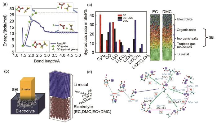
... [63];(b)锂金属电极浸入电解液的示意图(左)及单元初始配置(右)[64];(c)不同电解质SEI组分的分布(左).MD模拟的原子构型,SEI部分用括号标出[64];(d)根据不同途径还原EC/Li+ 和自由基终止反应的势能分布.ΔER 和ΔEB 分别表示反应能和反应势垒.青色为碳原子、白色为氢原子、红色为氧原子、紫色为锂原子、淡紫色大球体为电子[70]<strong>(a) Energy profile for breaking C<sub>2</sub>H<sub>4</sub> from o-EC/Li<sup>+</sup>, as obtained from QC calculations and gas phase simulations using ReaxFF at 10 K</strong><sup>[<xref ref-type="bibr" rid="R63">63</xref>]</sup>; <strong>(b) Schematic of a Li metal electrode dipped in an electrolyte (left) and initial configuration of the cell (right)</strong><sup>[<xref ref-type="bibr" rid="R64">64</xref>]</sup>; <strong>(c) Distribution of the SEI components for different electrolytes (left). Atomic configurations from MD simulations; the components of the SEI are identified (right)</strong><sup>[<xref ref-type="bibr" rid="R64">64</xref>]</sup>; <strong>(d) Potential energy profile for the reduction of EC/Li<sup>+</sup> and the radical termination reactions according to various pathways. Δ<i>E</i><sub>R</sub> and Δ<i>E</i><sub>B</sub> denote the reaction energy and reaction barrier, respectively. Color scheme: cyan, carbon; white, hydrogen; red, oxygen; purple, Li<sup>+</sup>; large blue sphere, electron</strong><sup>[<xref ref-type="bibr" rid="R70">70</xref>]</sup>Fig. 5
... [63]; (b) Schematic of a Li metal electrode dipped in an electrolyte (left) and initial configuration of the cell (right)[64]; (c) Distribution of the SEI components for different electrolytes (left). Atomic configurations from MD simulations; the components of the SEI are identified (right)[64]; (d) Potential energy profile for the reduction of EC/Li+ and the radical termination reactions according to various pathways. ΔER and ΔEB denote the reaction energy and reaction barrier, respectively. Color scheme: cyan, carbon; white, hydrogen; red, oxygen; purple, Li+; large blue sphere, electron[70]Fig. 5
<strong>(a) Energy profile for breaking C<sub>2</sub>H<sub>4</sub> from o-EC/Li<sup>+</sup>, as obtained from QC calculations and gas phase simulations using ReaxFF at 10 K</strong><sup>[<xref ref-type="bibr" rid="R63">63</xref>]</sup>; <strong>(b) Schematic of a Li metal electrode dipped in an electrolyte (left) and initial configuration of the cell (right)</strong><sup>[<xref ref-type="bibr" rid="R64">64</xref>]</sup>; <strong>(c) Distribution of the SEI components for different electrolytes (left). Atomic configurations from MD simulations; the components of the SEI are identified (right)</strong><sup>[<xref ref-type="bibr" rid="R64">64</xref>]</sup>; <strong>(d) Potential energy profile for the reduction of EC/Li<sup>+</sup> and the radical termination reactions according to various pathways. Δ<i>E</i><sub>R</sub> and Δ<i>E</i><sub>B</sub> denote the reaction energy and reaction barrier, respectively. Color scheme: cyan, carbon; white, hydrogen; red, oxygen; purple, Li<sup>+</sup>; large blue sphere, electron</strong><sup>[<xref ref-type="bibr" rid="R70">70</xref>]</sup>Fig. 5
... [64];(d)根据不同途径还原EC/Li+ 和自由基终止反应的势能分布.ΔER 和ΔEB 分别表示反应能和反应势垒.青色为碳原子、白色为氢原子、红色为氧原子、紫色为锂原子、淡紫色大球体为电子[70]<strong>(a) Energy profile for breaking C<sub>2</sub>H<sub>4</sub> from o-EC/Li<sup>+</sup>, as obtained from QC calculations and gas phase simulations using ReaxFF at 10 K</strong><sup>[<xref ref-type="bibr" rid="R63">63</xref>]</sup>; <strong>(b) Schematic of a Li metal electrode dipped in an electrolyte (left) and initial configuration of the cell (right)</strong><sup>[<xref ref-type="bibr" rid="R64">64</xref>]</sup>; <strong>(c) Distribution of the SEI components for different electrolytes (left). Atomic configurations from MD simulations; the components of the SEI are identified (right)</strong><sup>[<xref ref-type="bibr" rid="R64">64</xref>]</sup>; <strong>(d) Potential energy profile for the reduction of EC/Li<sup>+</sup> and the radical termination reactions according to various pathways. Δ<i>E</i><sub>R</sub> and Δ<i>E</i><sub>B</sub> denote the reaction energy and reaction barrier, respectively. Color scheme: cyan, carbon; white, hydrogen; red, oxygen; purple, Li<sup>+</sup>; large blue sphere, electron</strong><sup>[<xref ref-type="bibr" rid="R70">70</xref>]</sup>Fig. 5
... [64]; (c) Distribution of the SEI components for different electrolytes (left). Atomic configurations from MD simulations; the components of the SEI are identified (right)[64]; (d) Potential energy profile for the reduction of EC/Li+ and the radical termination reactions according to various pathways. ΔER and ΔEB denote the reaction energy and reaction barrier, respectively. Color scheme: cyan, carbon; white, hydrogen; red, oxygen; purple, Li+; large blue sphere, electron[70]Fig. 5
... [64]; (d) Potential energy profile for the reduction of EC/Li+ and the radical termination reactions according to various pathways. ΔER and ΔEB denote the reaction energy and reaction barrier, respectively. Color scheme: cyan, carbon; white, hydrogen; red, oxygen; purple, Li+; large blue sphere, electron[70]Fig. 5
<strong>(a) Energy profile for breaking C<sub>2</sub>H<sub>4</sub> from o-EC/Li<sup>+</sup>, as obtained from QC calculations and gas phase simulations using ReaxFF at 10 K</strong><sup>[<xref ref-type="bibr" rid="R63">63</xref>]</sup>; <strong>(b) Schematic of a Li metal electrode dipped in an electrolyte (left) and initial configuration of the cell (right)</strong><sup>[<xref ref-type="bibr" rid="R64">64</xref>]</sup>; <strong>(c) Distribution of the SEI components for different electrolytes (left). Atomic configurations from MD simulations; the components of the SEI are identified (right)</strong><sup>[<xref ref-type="bibr" rid="R64">64</xref>]</sup>; <strong>(d) Potential energy profile for the reduction of EC/Li<sup>+</sup> and the radical termination reactions according to various pathways. Δ<i>E</i><sub>R</sub> and Δ<i>E</i><sub>B</sub> denote the reaction energy and reaction barrier, respectively. Color scheme: cyan, carbon; white, hydrogen; red, oxygen; purple, Li<sup>+</sup>; large blue sphere, electron</strong><sup>[<xref ref-type="bibr" rid="R70">70</xref>]</sup>Fig. 5
<strong>(a) Li<sup>+ </sup>cation diffusion coefficients for ordered and amorphous SEI models consisting of Li<sub>2</sub>BDC and Li<sub>2</sub>EDC</strong><sup>[<xref ref-type="bibr" rid="R54">54</xref>]</sup>; <strong>(b) Snapshots highlighting the Li<sup>+</sup> distribution in ordered Li<sub>2</sub>BDC and Li<sub>2</sub>EDC, and amorphous Li<sub>2</sub>BDC, all at 393 K</strong>; <strong>Representative Li<sup>+</sup>-anion coordination in the double layer at (c) negative electrode potentials and (d) positive electrode potentials. Red and blue bars indicate the (<i>x</i>, <i>y</i>) plane of the anode and cathode surfaces, respectively</strong><sup>[<xref ref-type="bibr" rid="R76">76</xref>]</sup>Fig. 6
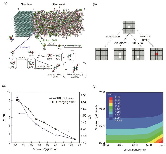
... [77];(b)在kMC模拟中选择发生的4种类型事件的示意图表示[79];(c, d)完全充电过程中SEI溶剂活化能对总充电时间和SEI厚度的影响[80](a) Model system and reaction scheme (cyan, carbon; red, oxygen; white, hydrogen; orange, phosphorus; green, fluorine; blue, lithium)<sup> [<xref ref-type="bibr" rid="R77">77</xref>]</sup>. (b) Schematic representation of the 4 types of events selected to occur in the kMC simulations<sup>[<xref ref-type="bibr" rid="R79">79</xref>]</sup>. (c, d) Effect of SEI solvent activation energy on the total charging time and SEI thickness during a full charging process <sup>[<xref ref-type="bibr" rid="R80">80</xref>]</sup>Fig. 7
... [77]. (b) Schematic representation of the 4 types of events selected to occur in the kMC simulations[79]. (c, d) Effect of SEI solvent activation energy on the total charging time and SEI thickness during a full charging process [80]Fig. 7
(a) Model system and reaction scheme (cyan, carbon; red, oxygen; white, hydrogen; orange, phosphorus; green, fluorine; blue, lithium)<sup> [<xref ref-type="bibr" rid="R77">77</xref>]</sup>. (b) Schematic representation of the 4 types of events selected to occur in the kMC simulations<sup>[<xref ref-type="bibr" rid="R79">79</xref>]</sup>. (c, d) Effect of SEI solvent activation energy on the total charging time and SEI thickness during a full charging process <sup>[<xref ref-type="bibr" rid="R80">80</xref>]</sup>Fig. 7
(a) Model system and reaction scheme (cyan, carbon; red, oxygen; white, hydrogen; orange, phosphorus; green, fluorine; blue, lithium)<sup> [<xref ref-type="bibr" rid="R77">77</xref>]</sup>. (b) Schematic representation of the 4 types of events selected to occur in the kMC simulations<sup>[<xref ref-type="bibr" rid="R79">79</xref>]</sup>. (c, d) Effect of SEI solvent activation energy on the total charging time and SEI thickness during a full charging process <sup>[<xref ref-type="bibr" rid="R80">80</xref>]</sup>Fig. 7
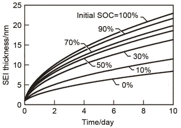
... [84]SEI film thickness under OCV as a function of time for various initial SOC. The simulations assumed an initial SEI thickness of 1 nm<sup>[<xref ref-type="bibr" rid="R84">84</xref>]</sup>Fig. 8


