In China, the goals of "peak carbon dioxide emissions" and "carbon neutrality" were proposed in December 2020. As a result, industrial and energy structures must be optimized and improved battery technology, developed. The electrode could represent the working mechanism and the corresponding evolution of electrochemical systems during battery operation. The inhomogeneity of the electrode process in a single battery becomes increasingly obvious as the energy density and size of batteries rise. However, in terms of space and time, the challenges apply to multi-scale, multi-level, multi-process, multi-step, and multi-field coupling issues in electrochemical batteries. In this review, we will focus on the electrode process of batteries with different active ions as well as related processes such as liquid mass transfer, surface charge electron transfer, and solid phase diffusion. The influences of voltage, overpotential, diffusion coefficient, and geometric parameters on battery design have been analyzed in typical examples of high energy-density batteries, high-power-density batteries, and long-life cycle batteries. Furthermore, the impact of the electrode process inhomogeneity mechanism on battery performance has been discussed. We examine the electrode processes of lithium-ion batteries and Al batteries using various types of in-situ characterization technologies from different manufacturers based on visualization and quantitative analysis. The findings may be used to better understand the electrode process, which can help with material design and structure optimization. The existing scientific and technical challenges are also analyzed by establishing the relationship between the electrode process and battery performance. Existing scientific and technical issues are also analyzed, promising a platform for rational design and manufacture of high-performance batteries.
Keywords:secondary battery
;
kinetic process
;
multiscale
;
in situ characterization technique
LYU Siqi. Progresses in visualization and quantitative analysis of the electrode process in rechargeable batteries[J]. Energy Storage Science and Technology, 2022, 11(3): 795-817
Table 2 Priority of design factors for different battery types (It is for reference only. Specific requirements for different application scenarios need to be considered)
Fig. 3
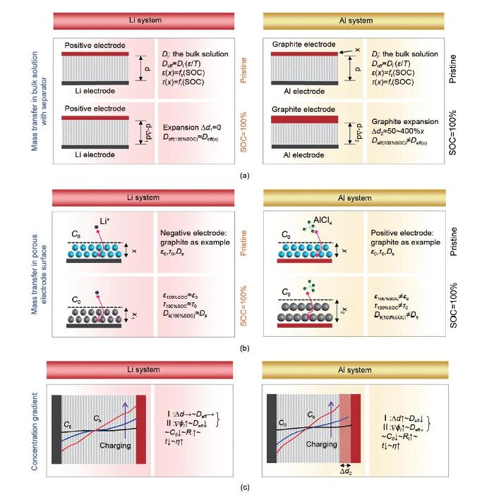
Schematic illustration of the ionic transport process in the (a) separator and (b) porous electrode in rechargeable lithium and aluminum battery systems, (c) schematic illustration of the concentration gradient of ions between the positive and negative electrode[17]
Fig. 4
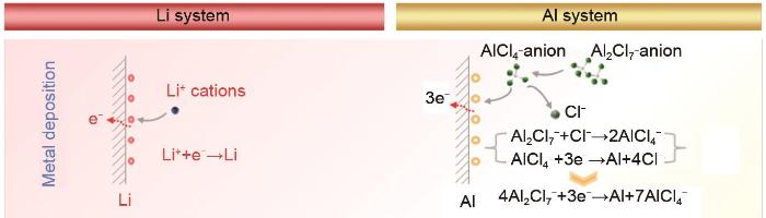
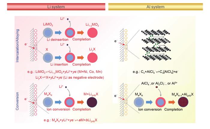
Schematic illustration of the electron transfer process in rechargeable lithium and aluminum battery systems (Such electron transfer process would be variable in different reaction mechanisms)[17]
Fig. 5
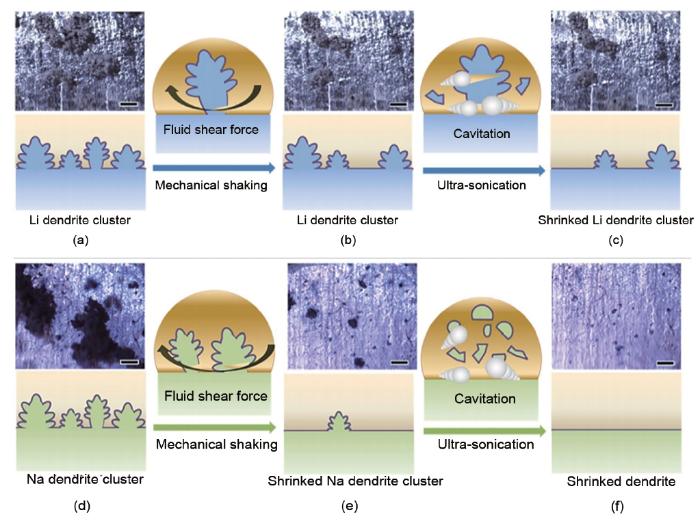
Mechanically stability under quasi-zero electrochemical field: (a) initial morphology of the as-plated lithium dendrites; lithium dendrites morphology after (b) mechanical shaking and (c) ultra-sonication; (d) initial morphology of sodium dendrites; sodium dendrites morphology after (e) mechanical shaking and (f) ultra-sonication (Schemes of the corresponding states are illustrated views)[27]
Fig. 6
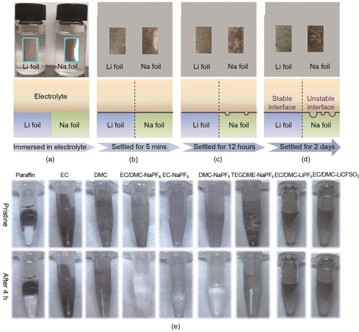
Chemical stability of lithium and sodium metals: (a) initial pristine lithium and sodium foils in the electrolytes, optical photographs of foils settled for (b) 5 min, (c) 12 hours and (d) 2 days (schemes of the corresponding states are illustrated from cross-section views), (e) sodium and lithium dendrites immersed in various electrolytes and observation after 4 h[27]
Fig. 7
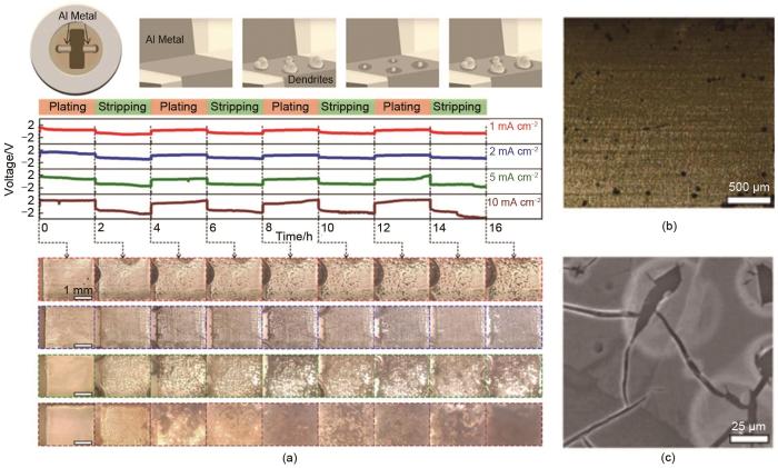
(a) scheme of in situ electrochemical reaction chamber (top left); schematic illustration of the Al nuclei deposited on the Al electrode (top right); experimental voltage of the in situ symmetrical battery (middle); and in situ top-view images for the first four cycles of Al electrode at areal current densities of 1, 2, 5 and 10 mA·cm-2; (b) typical optical image and (c) SEM image of the etched Al foil soaked in the electrolyte for 10 min[28]
Fig. 8
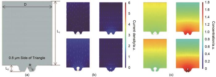
(a) a model used for simulations with concerns of curved surface in COMSOL, geometry after initial and the third deposition and stripping at (b, c left) 1 mA·cm-2 and (b, c right) 2 mA·cm-2, (b) the fields of current densities, (c) the fields of ion concentration[28]
Fig. 10
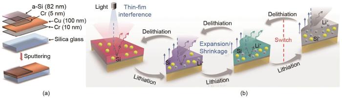
(a) schematic of the layered structure of the controllable coloration film; (b) mechanisms of the chromatic and achromic process of the controllable coloration films[29]
Fig. 11
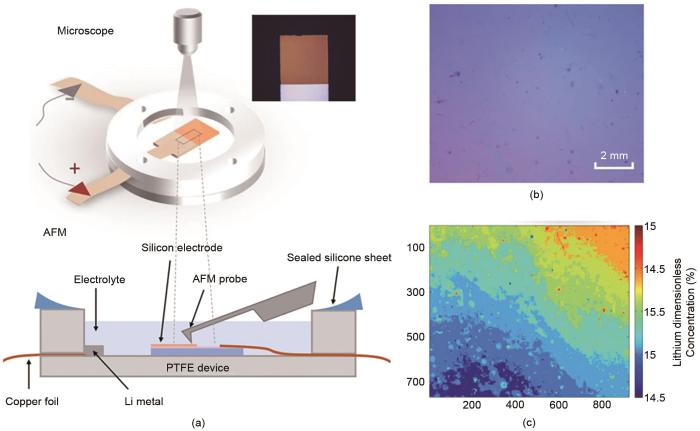
Schematic diagram of the in situ battery electrochemical system and the in situ battery optical imaging system: (a) the couter electrode is lithium in this battery; (b) image of lithium-ion wafer color calibration; and (d) lithium-ion dimensionless concentration distribution contour map[30]
Fig. 12
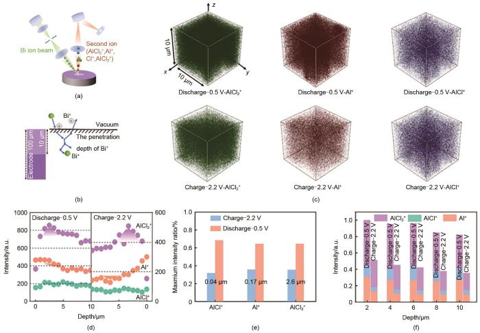
(a) the schematic diagram of TOF-SIMS; (b) the diagram of deep sputtering; (c) 3D images of the sputtered volume corresponding to the depth profiles at discharge -0.5 V and charge -2.2 V; (d) the depth profiles of secondary ions in aluminum series; (e) the ratio of three ions at the depth of their maximum contents during charge and discharge processes, and (f) the content ratio of three ions at different depths[11]
Fig. 15
(a) schematic diagram of the in situ Raman spectra battery electrochemical system; (b) in situ XRD spectra of the positive electrode in the solid-state AIB during charging/discharging; (c) XRD spectrum of the original carbon paper, and the corresponding charge/discharge curve at the current density of 20 mA·g-1; (d) in situ Raman spectra recorded from the graphite positive electrode in the charge and discharge processes[33]
Fig. 16
(a) schematic illustration of the X-ray CT test and data analysis; (b) reconstructed architecture of the composite positive electrode with different SOC; (c) schematic illustration of randomly selected areas in the reconstructed architecture of the composite positive electrode; (d) the volume ratio of graphite and pore in the composite positive electrode; (e, f) the volume distribution of graphite and pore in the composite positive electrode; (g, h) the volume ratio of graphite and pore in the different depth of the electrode[37]
Fig. 17
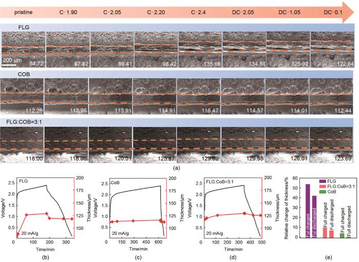
(a) in situ monitored SEM images of positive electrode materials at specific recorded states, where C and DC are the abbreviations of charge and discharge; (b)-(e) the volume changes of three types of positive electrode materials at specific recorded states[38]
Fig. 18
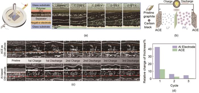
(a) equipment diagram of the optical battery, internal structure of a single battery, and in situ optical pictures of different charge/discharge states[39]; (b) DIBs assembled from all carbon electrodes as both cathode and anode; (c) in situ optical experiment images of the cathodes upon the first three cycles; (d) the relative change of the thickness of the cathode upon the first three cycles[40]
Fig. 19
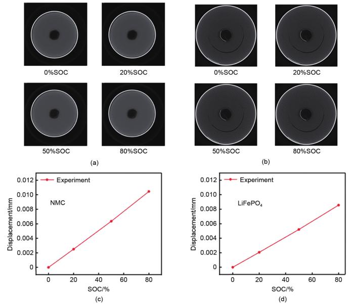
(a, b) the in situ CT slice images of LFP, NCM battery; (c, d) the radial displacement deformation of LFP, NCM battery; (e, f) radial displacement distribution at different radii during charge and discharge process[44]
Fig. 20
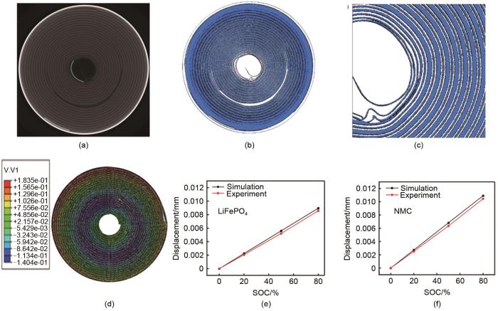
(a) the CT slice images; (b) three-dimensional reconstruction of solid image; (c) the detail of three-dimensional reconstruction of solid image; (d) cloud diagram of battery radial displacement distribution; comparison of simulation results and experiment results of outermost ring displacement of battery; (e) lithium iron phosphate battery (f) NCM battery[44]
Fig. 21
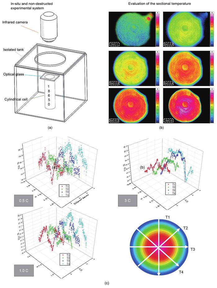
(a) a schematic diagram of the whole experimental setup; (b) infrared images of the sectional temperature at 1 C discharging rate; (c) temperature distribution at different angles with three different discharging rates (0.5, 1.0 and 3.0 C)[45]
Fig. 22
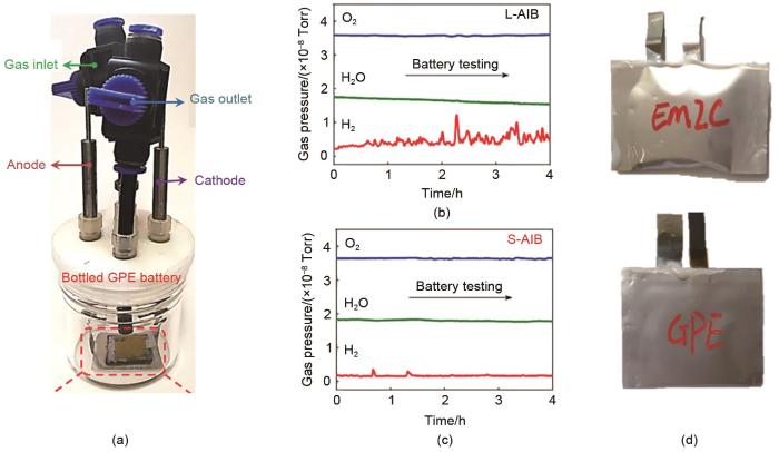
(a) the bottled battery with GPE electrolytes (the in situ gas partial pressure of the battery system with an real-time high-resolution mass spectrometer during charging/discharging process); (b) the GPE electrolyte system; (c) liquid electrolyte system; (d) The photos of the pouch cells after 300 cycles: the liquid electrolyte system and GPE electrolyte system[33]
Fig. 23
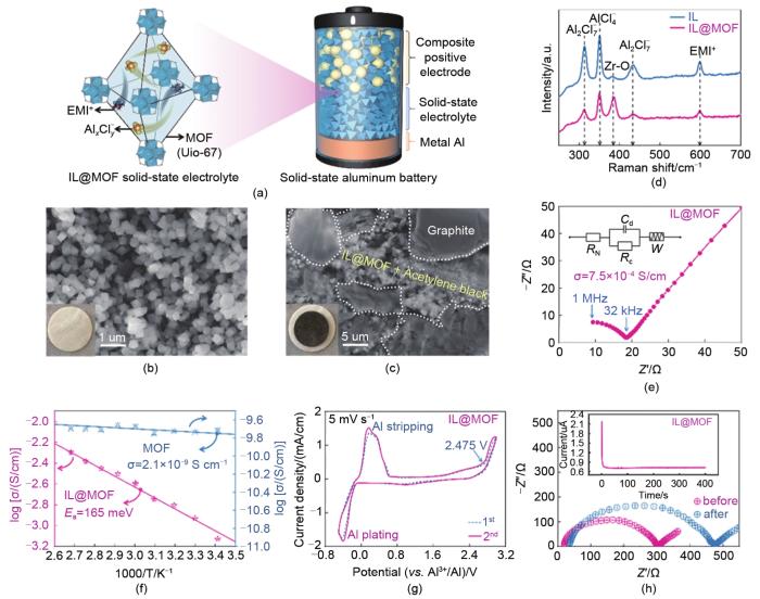
(a) schematic illustration of the magnification of internal structures in the IL@MOF electrolyte and the architecture of the quasi-solid-state aluminum battery. The migrating Al x Cl y-and EMIm+ ions are randomly displayed in the pores of the Uio-67 MOF, and the composite positive electrode in quasi-solid-state aluminum battery consists of graphite (yellow ball), IL@MOF electrolyte (blue octahedron) and acetylene black (black ball), (b) SEM morphology of IL@MOF particle, and the inset shows the photos of IL@MOF pellet, (c) SEM morphology of the composite positive electrode (inset: the photos of quasi-solid-state electrolyte/positive electrode pellets), (d) Raman spectra of the pristine IL and IL@MOF electrolyte, (e) EIS plot of the symmetric cell (Mo | IL@MOF | Mo) at room temperature with the equivalent circuit, (f) arrhenius plots for the ionic conductivity of pure MOF and IL@MOF, (g) CV curve for the first two cycles of the asymmetric cell (Al | IL@MOF | Mo) at the scan rate of 5 mV/s, (h) EIS plot of symmetric cells (Al | IL@MOF | Al) before and after polarization[37]
Fig. 24
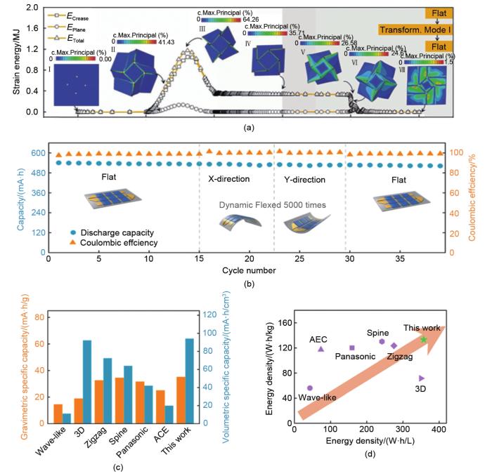
(a) the FEA results of the strain energy with the processes of mechanical folding from the initial flat state to transformation modes I, with a subsequent self-deployment process via thermal stimulus[47], (b) cycle performance of the snake-origami batteries under continuous mechanical loading at 0.5 C (x-axis was described as cycle numbers of battery working), (c) the state-of-the-art of cell-scale energy density for the reported flexible batteries, along with comparison of energy density in snake-origami batteries, (d) cell-scale specific capacity of previous reported flexible batteries compared with snake-origami batteries[48]
TAFEL J. Über Die polarisation Bei kathodischer wasserstoffentwicklung[J]. Zeitschrift Für Physikalische Chemie, 1905, 50U(1): 641-712.
BUTLER J A. Studies in heterogeneous equilibria. Part II.—The kinetic interpretation of the Nernst theory of electromotive force[J]. Transactions of the Faraday Society, 1924, 19: 729-733.
ERDEY-GRÚZ T, VOLMER M. Zur theorie der wasserstoff überspannung[J]. Zeitschrift Für Physikalische Chemie, 1930, 150A(1): 203-213.
FRUMKIN A. Wasserstoffüberspannung und struktur der doppelschicht[J]. Zeitschrift Für Physikalische Chemie, 1933, 164: 121-133.
BOCKRIS J O, POTTER E C. The mechanism of the cathodic hydrogen evolution reaction[J]. Journal of the Electrochemical Society, 1952, 99(4): 169-186.
GRAHAME D C. Properties of the electrical double layer at a mercury surface. I. Methods of measurement and interpretation of results[J]. Journal of the American Chemical Society, 1941, 63(5): 1207-1215.
LEVICH V. The theory of concentration overpotential[J]. Acta Physicochim URSS, 1942, 17: 257-307.
LIBBY W F. The potential usefulness of natural tritium[J]. Proceedings of the National Academy of Sciences of the United States of America, 1953, 39(4): 245-247.
MARCUS R A. On the theory of oxidation-reduction reactions involving electron transfer. I[J]. The Journal of Chemical Physics, 1956, 24(5): 966-978.
ŠEVČÍK A. Oscillographic polarography with periodical triangular voltage[J]. Collection of Czechoslovak Chemical Communications, 1948, 13: 349-377.
GERISCHER H. Kinetik der entladung einfacher und komplexer zink-ionen[J]. Zeitschrift Für Physikalische Chemie, 1953, 202(1): 302-317.
GERISCHER H. Über den ablauf von redoxreaktionen an metallen und an halbleitern[J]. Zeitschrift Für Physikalische Chemie, 1960, 26(3/4): 223-247.
CALEF D F, WOLYNES P G. Classical solvent dynamics and electron transfer. II. Molecular aspects[J]. The Journal of Chemical Physics, 1983, 78(1): 470-482.
DE LEVIE R. On porous electrodes in electrolyte solutions: I. Capacitance effects[J]. Electrochimica Acta, 1963, 8(10): 751-780.
TU J G, SONG W L, LEI H P, et al. Nonaqueous rechargeable aluminum batteries: Progresses, challenges, and perspectives[J]. Chemical Reviews, 2021, 121(8): 4903-4961.
LIANG C P, LONGO R C, KONG F T, et al. Obstacles toward unity efficiency of LiNi1-2xCoxMnxO2 (x = 0~1/3) (NCM) cathode materials: Insights from ab initio calculations[J]. Journal of Power Sources, 2017, 340: 217-228.
ZHANG C Y, HE R, ZHANG J C, et al. Amorphous carbon-derived nanosheet-bricked porous graphite as high-performance cathode for aluminum-ion batteries[J]. ACS Applied Materials & Interfaces, 2018, 10(31): 26510-26516.
VON LÜDERS C, KEIL J, WEBERSBERGER M, et al. Modeling of lithium plating and lithium stripping in lithium-ion batteries[J]. Journal of Power Sources, 2019, 414: 41-47.
KRAUSKOPF T, RICHTER F H, ZEIER W G, et al. Physicochemical concepts of the lithium metal anode in solid-state batteries[J]. Chemical Reviews, 2020, 120(15): 7745-7794.
BOYLE D T, KONG X, PEI A, et al. Transient voltammetry with ultramicroelectrodes reveals the electron transfer kinetics of lithium metal anodes[J]. ACS Energy Letters, 2020, 5(3): 701-709.
PAN C J, YUAN C Z, ZHU G Z, et al. An operando X-ray diffraction study of chloroaluminate anion-graphite intercalation in aluminum batteries[J]. Proceedings of the National Academy of Sciences of the United States of America, 2018, 115(22): 5670-5675.
GIFFORD P R, PALMISANO J B. An aluminum/chlorine rechargeable cell employing a room temperature molten salt electrolyte[J]. Journal of the Electrochemical Society, 1988, 135(3): 650-654.
MAMANTOV G, TORSI G. Potentiometric study of the dissociation of the tetrachloroaluminate ion in molten sodium chloroaluminates at 175-400.deg[J]. Inorganic Chemistry, 1971, 10(9): 1900-1902.
KARPINSKI Z J, OSTERYOUNG R A. Potentiometric studies of the chlorine electrode in ambient-temperature chloroaluminate ionic liquids: Determination of equilibrium constants for tetrachloroaluminate ion dissociation[J]. Inorganic Chemistry, 1985, 24(14): 2259-2264.
HONG Y S, LI N, CHEN H S, et al. In operando observation of chemical and mechanical stability of Li and Na dendrites under quasi-zero electrochemical field[J]. Energy Storage Materials, 2018, 11: 118-126.
SHE D M, SONG W L, HE J, et al. Erratum: surface evolution of aluminum electrodes in non-aqueous aluminum batteries[J]. Journal of the Electrochemical Society, 2020, 167(14): doi: 10.1149/1945-7111/abbb09.
BAO Y H, HAN Y, YANG L, et al. Bioinspired controllable electro-chemomechanical coloration films[J]. Advanced Functional Materials, 2019, 29(2): doi: 10.1002/adfm.201806383.
CHEN H S, HAN Y, YANG L, et al. A method for analyzing two-dimensional lithium ion concentration in the nano silicon films[J]. Applied Physics Letters, 2019, 115(26): doi: 10.1063/1.5132578.
HAN X, LI S J, SONG W L, et al. Stable high-capacity organic aluminum-porphyrin batteries[J]. Advanced Energy Materials, 2021, 11(32): doi: 10.1002/aenm.202101446.
HAN D, CAO M S, LI N, et al. Initial electrode kinetics of anion intercalation and de-intercalation in nonaqueous Al-graphite batteries[J]. Chinese Journal of Chemistry, 2021, 39(1): 157-164.
YU Z J, JIAO S Q, LI S J, et al. Flexible stable solid-state Al-ion batteries[J]. Advanced Functional Materials, 2019, 29(1): doi: 10.1002/adfm.201806799.
DONG K, MARKÖTTER H, SUN F, et al. In situ and operando tracking of microstructure and volume evolution of silicon electrodes by using synchrotron X-ray imaging[J]. ChemSusChem, 2019, 12(1): 261-269.
EBNER M, MARONE F, STAMPANONI M, et al. Visualization and quantification of electrochemical and mechanical degradation in Li ion batteries[J]. Science, 2013, 342(6159): 716-720.
RAHE C, KELLY S T, RAD M N, et al. Nanoscale X-ray imaging of ageing in automotive lithium ion battery cells[J]. Journal of Power Sources, 2019, 433: doi: 10.1016/j.jpowsour.2019.05.039.
CHEN L L, LI N, SHI H F, et al. Stable wide-temperature and low volume expansion Al batteries: Integrating few-layer graphene with multifunctional cobalt boride nanocluster as positive electrode[J]. Nano Research, 2020, 13(2): 419-429.
CHEN L L, SONG W L, LI N, et al. Nonmetal Current collectors: The key component for high-energy-density aluminum batteries[J]. Advanced Materials, 2020, 32(42): doi: 10.1002/adma.202001212.
ZHOU Z L, LI N, YANG Y Z, et al. Ultra-lightweight 3D carbon current collectors: Constructing all-carbon electrodes for stable and high energy density dual-ion batteries[J]. Advanced Energy Materials, 2018, 8(26): doi: 10.1002/aenm.201801439.
ZHANG J N, LI Q H, OUYANG C Y, et al. Trace doping of multiple elements enables stable battery cycling of LiCoO2 at 4.6 V[J]. Nature Energy, 2019, 4(7): 594-603.
BOND T, ZHOU J G, CUTLER J. Electrode stack geometry changes during gas evolution in pouch-cell-type lithium ion batteries[J]. Journal of the Electrochemical Society, 2016, 164(1): A6158-A6162.
CHEN C C, WEI Y, ZHAO Z B, et al. Investigation of the swelling failure of lithium-ion battery packs at low temperatures using 2D/3D X-ray computed tomography[J]. Electrochimica Acta, 2019, 305: 65-71.
WENG J W. Experimental characterization and simulation research on the internal strain field of lithium ion cylindrical battery[D]. Beijing: Beijing Institute of Technology, 2021.
DU X, WU Q, WANG Y N, et al. Visualizing two-dimensional internal temperature distribution in cylindrical Li-ion cells[J]. Journal of Power Sources, 2020, 446: doi: 10.1016/j.jpowsour. 2019.227343.
TAN J, MATZ J, DONG P, et al. A growing appreciation for the role of LiF in the solid electrolyte interphase[J]. Advanced Energy Materials, 2021, 11(16): doi: 10.1002aenm.202100046.
WANG L C, SONG W L, ZHANG Y J, et al. Active reconfigurable tristable square-twist origami[J]. Advanced Functional Materials, 2020, 30(13): doi: 10.1002/adfm.201909087.
(a) the schematic diagram of TOF-SIMS; (b) the diagram of deep sputtering; (c) 3D images of the sputtered volume corresponding to the depth profiles at discharge -0.5 V and charge -2.2 V; (d) the depth profiles of secondary ions in aluminum series; (e) the ratio of three ions at the depth of their maximum contents during charge and discharge processes, and (f) the content ratio of three ions at different depths<sup>[<xref ref-type="bibr" rid="R11">11</xref>]</sup>Fig. 12<strong>1.3</strong> 不同电池体系的固相扩散过程
... [17]Schematic illustration of the ionic transport process in the (a) separator and (b) porous electrode in rechargeable lithium and aluminum battery systems, (c) schematic illustration of the concentration gradient of ions between the positive and negative electrode<sup>[<xref ref-type="bibr" rid="R17">17</xref>]</sup>Fig. 3<strong>1.2</strong> 不同电池体系的表面电子转移过程1.2.1 金属表面电子转移
Schematic illustration of the electron transfer process in rechargeable lithium and aluminum battery systems (Such electron transfer process would be variable in different reaction mechanisms)<sup>[<xref ref-type="bibr" rid="R17">17</xref>]</sup>Fig. 4
<strong>(a) a model used for simulations with concerns of curved surface in COMSOL, geometry after initial and the third deposition and stripping at (b, c left) 1 mA·cm</strong><sup>-</sup><strong><sup>2</sup> and (b, c right) 2 mA·cm</strong><sup>-</sup><strong><sup>2</sup>, (b) the fields of current densities, (c) the fields of ion concentration</strong><sup>[<xref ref-type="bibr" rid="R28">28</xref>]</sup>Fig. 8
The electron transfer process in lithium battery and aluminum battery in different reaction mechanisms<sup>[<xref ref-type="bibr" rid="R17">17</xref>]</sup>Fig. 91.2.2 非金属表面电子转移
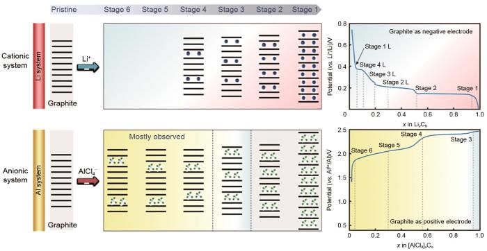
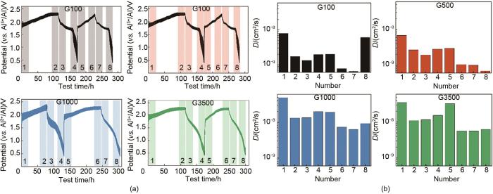
Schematic illustration of the diffusion process of ions in the solid materials in rechargeable lithium and aluminum battery systems<sup>[<xref ref-type="bibr" rid="R17">17</xref>]</sup>Fig. 13
... [27]Mechanically stability under quasi-zero electrochemical field: (a) initial morphology of the as-plated lithium dendrites; lithium dendrites morphology after (b) mechanical shaking and (c) ultra-sonication; (d) initial morphology of sodium dendrites; sodium dendrites morphology after (e) mechanical shaking and (f) ultra-sonication (Schemes of the corresponding states are illustrated views)<sup>[<xref ref-type="bibr" rid="R27">27</xref>]</sup>Fig. 5
Chemical stability of lithium and sodium metals: (a) initial pristine lithium and sodium foils in the electrolytes, optical photographs of foils settled for (b) 5 min, (c) 12 hours and (d) 2 days (schemes of the corresponding states are illustrated from cross-section views), (e) sodium and lithium dendrites immersed in various electrolytes and observation after 4 h<sup>[<xref ref-type="bibr" rid="R27">27</xref>]</sup>Fig. 6
... [28]<strong>(a) scheme of in situ electrochemical reaction chamber (top left); schematic illustration of the Al nuclei deposited on the Al electrode (top right); experimental voltage of the in situ symmetrical battery (middle); and in situ top-view images for the first four cycles of Al electrode at areal current densities of 1, 2, 5 and 10 mA·cm</strong><sup>-</sup><strong><sup>2</sup>; (b) typical optical image and (c) SEM image of the etched Al foil soaked in the electrolyte for 10 min</strong><sup>[<xref ref-type="bibr" rid="R28">28</xref>]</sup>Fig. 7
<strong>(a) a model used for simulations with concerns of curved surface in COMSOL, geometry after initial and the third deposition and stripping at (b, c left) 1 mA·cm</strong><sup>-</sup><strong><sup>2</sup> and (b, c right) 2 mA·cm</strong><sup>-</sup><strong><sup>2</sup>, (b) the fields of current densities, (c) the fields of ion concentration</strong><sup>[<xref ref-type="bibr" rid="R28">28</xref>]</sup>Fig. 8
The electron transfer process in lithium battery and aluminum battery in different reaction mechanisms<sup>[<xref ref-type="bibr" rid="R17">17</xref>]</sup>Fig. 91.2.2 非金属表面电子转移
The electron transfer process in lithium battery and aluminum battery in different reaction mechanisms<sup>[<xref ref-type="bibr" rid="R17">17</xref>]</sup>Fig. 91.2.2 非金属表面电子转移
... [29](a) schematic of the layered structure of the controllable coloration film; (b) mechanisms of the chromatic and achromic process of the controllable coloration films<sup>[<xref ref-type="bibr" rid="R29">29</xref>]</sup>Fig. 10
... [30]Schematic diagram of the in situ battery electrochemical system and the in situ battery optical imaging system: (a) the couter electrode is lithium in this battery; (b) image of lithium-ion wafer color calibration; and (d) lithium-ion dimensionless concentration distribution contour map<sup>[<xref ref-type="bibr" rid="R30">30</xref>]</sup>Fig. 11
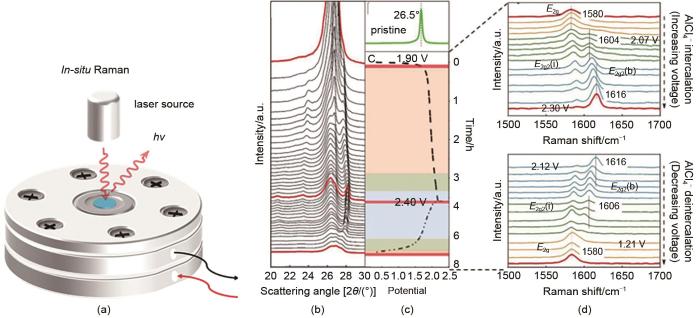
... [33]<strong>(a) schematic diagram of the in situ Raman spectra battery electrochemical system; (b) <i>in situ</i> XRD spectra of the positive electrode in the solid-state AIB during charging/discharging; (c) XRD spectrum of the original carbon paper, and the corresponding charge/discharge curve at the current density of 20 mA·g</strong><sup>-</sup><strong><sup>1</sup>; (d) <i>in situ</i> Raman spectra recorded from the graphite positive electrode in the charge and discharge processes</strong><sup>[<xref ref-type="bibr" rid="R33">33</xref>]</sup>Fig. 15
... [33](a) the bottled battery with GPE electrolytes (the in situ gas partial pressure of the battery system with an real-time high-resolution mass spectrometer during charging/discharging process); (b) the GPE electrolyte system; (c) liquid electrolyte system; (d) The photos of the pouch cells after 300 cycles: the liquid electrolyte system and GPE electrolyte system<sup>[<xref ref-type="bibr" rid="R33">33</xref>]</sup>Fig. 22<strong>1.6</strong> 电池设计制造与电极过程的关系小结
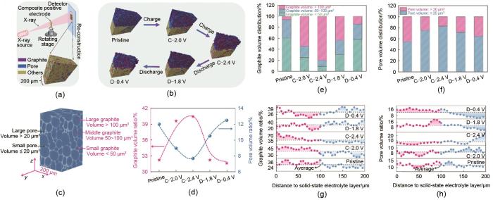
... [37](a) schematic illustration of the X-ray CT test and data analysis; (b) reconstructed architecture of the composite positive electrode with different SOC; (c) schematic illustration of randomly selected areas in the reconstructed architecture of the composite positive electrode; (d) the volume ratio of graphite and pore in the composite positive electrode; (e, f) the volume distribution of graphite and pore in the composite positive electrode; (g, h) the volume ratio of graphite and pore in the different depth of the electrode<sup>[<xref ref-type="bibr" rid="R37">37</xref>]</sup>Fig. 16
... [37]<strong>(a) schematic illustration of the magnification of internal structures in the IL@MOF electrolyte and the architecture of the quasi-solid-state aluminum battery. The migrating Al <i><sub>x</sub></i> Cl <i><sub>y</sub></i></strong><sup>-</sup><strong>and EMIm<sup>+</sup> ions are randomly displayed in the pores of the Uio-67 MOF, and the composite positive electrode in quasi-solid-state aluminum battery consists of graphite (yellow ball), IL@MOF electrolyte (blue octahedron) and acetylene black (black ball), (b) SEM morphology of IL@MOF particle, and the inset shows the photos of IL@MOF pellet, (c) SEM morphology of the composite positive electrode (inset: the photos of quasi-solid-state electrolyte/positive electrode pellets), (d) Raman spectra of the pristine IL and IL@MOF electrolyte, (e) EIS plot of the symmetric cell (Mo | IL@MOF | Mo) at room temperature with the equivalent circuit, (f) arrhenius plots for the ionic conductivity of pure MOF and IL@MOF, (g) CV curve for the first two cycles of the asymmetric cell (Al | IL@MOF | Mo) at the scan rate of 5 mV/s, (h) EIS plot of symmetric cells (Al | IL@MOF | Al) before and after polarization</strong><sup>[<xref ref-type="bibr" rid="R37">37</xref>]</sup>Fig. 23
... [38](a) <i>in situ</i> monitored SEM images of positive electrode materials at specific recorded states, where C and DC are the abbreviations of charge and discharge; (b)-(e) the volume changes of three types of positive electrode materials at specific recorded states<sup>[<xref ref-type="bibr" rid="R38">38</xref>]</sup>Fig. 17
... [39];(b) 全碳电极作为正极和负极组装的双离子电池;(c) 前三个周期原位光学实验图像;(d) 前三个周期内正极厚度相对变化[40](a) equipment diagram of the optical battery, internal structure of a single battery, and in situ optical pictures of different charge/discharge states<sup>[<xref ref-type="bibr" rid="R39">39</xref>]</sup>; (b) DIBs assembled from all carbon electrodes as both cathode and anode; (c) <i>in situ</i> optical experiment images of the cathodes upon the first three cycles; (d) the relative change of the thickness of the cathode upon the first three cycles<sup>[<xref ref-type="bibr" rid="R40">40</xref>]</sup>Fig. 18<strong>1.4</strong> 电极过程引起的结构场效应可视化与定量化技术
... [39]; (b) DIBs assembled from all carbon electrodes as both cathode and anode; (c) in situ optical experiment images of the cathodes upon the first three cycles; (d) the relative change of the thickness of the cathode upon the first three cycles[40]Fig. 18<strong>1.4</strong> 电极过程引起的结构场效应可视化与定量化技术
... [40](a) equipment diagram of the optical battery, internal structure of a single battery, and in situ optical pictures of different charge/discharge states<sup>[<xref ref-type="bibr" rid="R39">39</xref>]</sup>; (b) DIBs assembled from all carbon electrodes as both cathode and anode; (c) <i>in situ</i> optical experiment images of the cathodes upon the first three cycles; (d) the relative change of the thickness of the cathode upon the first three cycles<sup>[<xref ref-type="bibr" rid="R40">40</xref>]</sup>Fig. 18<strong>1.4</strong> 电极过程引起的结构场效应可视化与定量化技术
... [44](a, b) the in situ CT slice images of LFP, NCM battery; (c, d) the radial displacement deformation of LFP, NCM battery; (e, f) radial displacement distribution at different radii during charge and discharge process<sup>[<xref ref-type="bibr" rid="R44">44</xref>]</sup>Fig. 19
(a) the CT slice images; (b) three-dimensional reconstruction of solid image; (c) the detail of three-dimensional reconstruction of solid image; (d) cloud diagram of battery radial displacement distribution; comparison of simulation results and experiment results of outermost ring displacement of battery; (e) lithium iron phosphate battery (f) NCM battery<sup>[<xref ref-type="bibr" rid="R44">44</xref>]</sup>Fig. 20
... [45](a) a schematic diagram of the whole experimental setup; (b) infrared images of the sectional temperature at 1 C discharging rate; (c) temperature distribution at different angles with three different discharging rates (0.5, 1.0 and 3.0 C)<sup>[<xref ref-type="bibr" rid="R45">45</xref>]</sup>Fig. 21<strong>1.5</strong> 产气等副反应过程的在线定量化分析技术
... [47];(b) 蛇形折纸电池在0.5 ℃连续机械负载下的循环性能(x 轴表示电池工作的循环次数);(c) 已报道的柔性电池的电池尺度能量密度的最新进展,并比较了蛇形折纸电池的能量密度;(d) 与蛇形折纸电池相比,先前报道的柔性电池的细胞规模比容量[48](a) the FEA results of the strain energy with the processes of mechanical folding from the initial flat state to transformation modes I, with a subsequent self-deployment process via thermal stimulus<sup>[<xref ref-type="bibr" rid="R47">47</xref>]</sup>, (b) cycle performance of the snake-origami batteries under continuous mechanical loading at 0.5 C (<i>x</i>-axis was described as cycle numbers of battery working), (c) the state-of-the-art of cell-scale energy density for the reported flexible batteries, along with comparison of energy density in snake-origami batteries, (d) cell-scale specific capacity of previous reported flexible batteries compared with snake-origami batteries<sup>[<xref ref-type="bibr" rid="R48">48</xref>]</sup>Fig. 24
... [47], (b) cycle performance of the snake-origami batteries under continuous mechanical loading at 0.5 C (x-axis was described as cycle numbers of battery working), (c) the state-of-the-art of cell-scale energy density for the reported flexible batteries, along with comparison of energy density in snake-origami batteries, (d) cell-scale specific capacity of previous reported flexible batteries compared with snake-origami batteries[48]Fig. 24
(a) the FEA results of the strain energy with the processes of mechanical folding from the initial flat state to transformation modes I, with a subsequent self-deployment process via thermal stimulus<sup>[<xref ref-type="bibr" rid="R47">47</xref>]</sup>, (b) cycle performance of the snake-origami batteries under continuous mechanical loading at 0.5 C (<i>x</i>-axis was described as cycle numbers of battery working), (c) the state-of-the-art of cell-scale energy density for the reported flexible batteries, along with comparison of energy density in snake-origami batteries, (d) cell-scale specific capacity of previous reported flexible batteries compared with snake-origami batteries<sup>[<xref ref-type="bibr" rid="R48">48</xref>]</sup>Fig. 24


