With the rapid development of commercial lithium-ion batteries (LIBs), safety has become an increasingly prominent and urgent problem. As one of the important cases causing LIBs accidents, thermal runaway is closely related to the thermal stability of the solid electrolyte interface (SEI) on the graphite anode. Therefore, the properties of SEI must be deeply understood and accurately controlled to improve the safety of LIBs. Herein, the composition, structure, and formation principle of SEI are briefly introduced, and its key role in the processes of thermal runaway is emphasized. Second, the unsafe factors related to SEI and the mechanisms in the process of thermal runaway are discussed. We analyze the decomposition of SEI, the pyrolysis of lithiated graphite, the release of combustible gas, lithium plating, and the influence of transition metals on SEI. Our results indicate that the thermal stability and Li+ conductivity of SEI must be improved at the same time to effectively enhance the safety of LIBs. According to the decisive relationship between the structure and composition, properties, and properties of materials, researchers have conducted extensive research on the modification of SEI. The characteristics of SEI can be tuned by adjusting its electrolyte composition or introducing additives into the negative electrode to regulate the SEI insitu and constructing an artificial SEI with inorganic or organic components. Finally, we present the future research and regulation direction of SEI, which provides a theoretical basis and experimental guidance for improving the safety of LIBs.
ZHANG Jiayi. Solid electrolyte interphase (SEI) on graphite anode correlated with thermal runaway of lithium-ion batteries[J]. Energy Storage Science and Technology, 2023, 12(7): 2105-2118
锂离子电池(LIBs)因其在高效储能和环境友好[1]方面的巨大潜力而逐渐成为全球电能存储的主流,投放市场的电池容量和数量在近年来出现了惊人的增长[2]。据统计,LIBs装机总容量已从2010年的29.6 GWh增长至2022年的750 GWh,预计到2030年将突破2500 GWh[3]。然而,随着LIBs的快速普及和电动汽车[4]、智能电网[5]等的推广和应用,在能量密度、倍率性能、循环寿命、成本和安全性能等各个方面对LIBs提出了更高的要求。然而,目前LIBs的安全性能还不够理想。据统计,新能源电动车燃烧事故中,约60%来自三元LIBs。2011—2021年间,全球共报道32起储能电站起火爆炸事故,其中25起与LIBs相关。Samsung Note7手机爆炸和Tesla Model S起火等事件,不仅对人们的生命财产造成了极大的威胁,而且对LIBs产业产生了巨大冲击[6-7]。热失控是LIBs失效引发安全事故的重要形式之一[6, 8-9]。电池内部温度升高会引发一系列放热反应;热量在电池内部积累,进一步加快了反应速率,造成温度急剧升高、产生可燃气体并破坏电池内部结构,甚至导致火灾或爆炸[9]。此外,电池内部发生短路也会造成电池温度急剧升高[10-11]。
LIBs的热失控并非单一因素所致,而更像是多米诺骨牌,由一系列连锁反应组成,其中固体电解质界面(SEI)膜的分解位于这些反应的起始位置[12]。因此,通过调控SEI膜来抑制或延缓热失控过程成为一种顺理成章的思路和方法。近年来,随着表征技术的不断进步,人们逐渐加深了对SEI膜的认识,在调控SEI膜来提升电池安全性方面也积累了不少经验。此外,研究表明,负极材料是电池内形成SEI膜的主要位置[8]。石墨凭借其高容量(372 mAh/g)、低工作电位(约0.1 V vs. Li+/Li)、低成本和长循环寿命[13-14],自20世纪90年代初至今始终作为商用LIBs的主要负极材料之一,也是未来不可完全替代的关键负极之一。鉴于此,以石墨负极为研究对象,系统介绍SEI膜的生成、分解与调控,及其与电池热失控之间的关系。
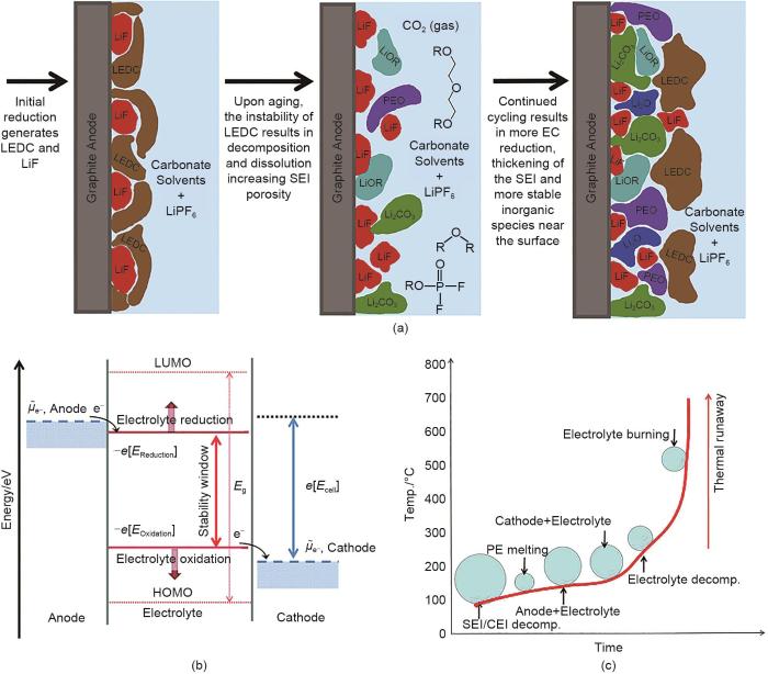
由SEI膜的形成机制可知,其物质组成与所用电解液的类型和分解路径直接相关[20-21]。商用LIBs电解液一般由LiPF6溶解于有机碳酸酯混合溶剂构成,包括环状碳酸酯(如碳酸乙烯酯EC)和链状碳酸酯(如碳酸二甲酯DMC、碳酸二乙酯DEC和碳酸甲乙酯EMC)。与链状碳酸酯相比,EC更容易发生还原分解[22]。因此,SEI膜的主要成分是由EC还原生成的二碳酸乙烯锂(LEDC)和LiPF6生成的LiF和Li x PO y F z[23-24],反应如下:
Fig. 1
(a) Schematic of SEI formation on graphite anode[22]; (b) Thermodynamics of SEI formation on anode and cathode, where μe-,Anode and μe-,Cathode are the electrochemical potentials of the anode and cathode respectively, and the stability window of the electrolyte is the difference between the energies of LUMO and HOMO, expressed as Eg[30]; (c) Qualitative description of chain reactions during thermal runaway[5]
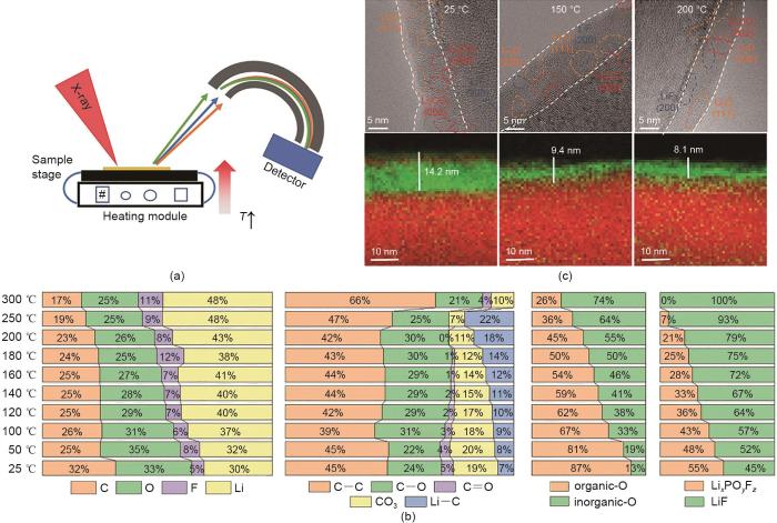
SEI膜的热分解作为热失控过程的第1步,需要充分了解它的分解过程。Wu等[34]利用原位加热X射线光电子能谱(XPS)和低温透射电子显微镜(cryo-TEM)等表征手段,原位和非原位地监测具有类石墨结构的气相生长碳纤维(VGCF)表面SEI膜的热分解过程(图2)。如图2(a)所示,采用特殊设计的载物台可以允许使用XPS原位监测样品在加热过程中的成分演变。根据对XPS谱的定量分析发现[图2(b)],SEI膜中的部分有机物在25~50 ℃较低温度下已经开始发生分解,形成Li2O、LiF和Li2CO3等无机物。在持续加热过程中,无机化合物中的C和O含量不断增加而有机化合物中的C和O相应逐渐减少;LiF含量增加而Li x PO y F z 含量显著降低;这说明有机物和Li x PO y F z 均发生了分解。其中Li x PO y F z 在200~250 ℃时发生完全分解,对应反应为:
Fig. 2
(a) Schematic of in-situ heating XPS; (b) Quantitative analysis of the XPS survey spectra, C 1s, O 1s, and F 1s spectra from the lithiated VGCF during the temperature rising from 25 ℃ to 300 ℃; (c) Cryo-TEM images of SEI on the lithiated VGCF at 25, 150, 200 ℃ and their corresponding elemental distribution of C (marked in red) and O (marked in green) based on EELS map scanning[34]
Fig. 3
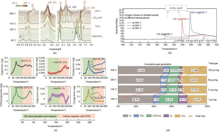
(a) In-situ XRD patterns of the lithiated graphite anode when heated from 25 to 280 ℃ at 2 ℃/min; (b) The influence of oxygen on the lithiated graphite anode at different temperatures during the DSC measurements; (c) In-situ monitoring the evolution of H2, CH3·, CH4, CO/C2H4, O2, and CO2 during heating of the lithiated graphite anode; (d) The quantitative analysis of the gas cumulative ratio at 100, 150, 200, and 250 ℃, respectively[39]
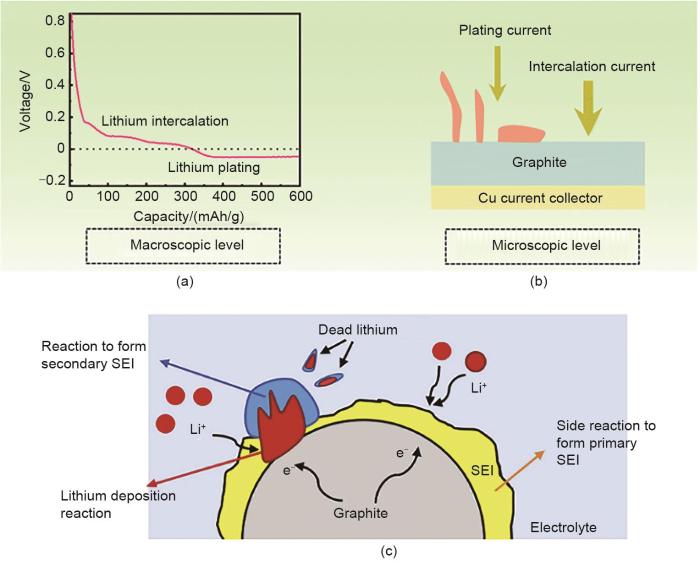
如图4(a)所示,锂沉积发生在局部电位低于0 V (vs. Li+/Li)时,而Li+嵌入石墨的电位高于此值(约0.1 V vs. Li+/Li);因此,在热力学上,锂嵌入石墨要优先于锂沉积发生[46]。然而,在实际应用的全电池中,尤其在快充、低温和长循环条件下,由于欧姆电位降、浓差过电势、电荷转移过电势等多种极化效应将负极电位降低至锂沉积阈值。在微观层面上[图4(b)],锂沉积和锂插层共存在于全电池充电过程中,表达式分别为[47]:
Fig. 4
(a) Macroscopic and (b) microscopic mechanisms of lithium plating during Li+ intercalation into graphite[4]; (c) Effect of lithium plating on SEI[45]
Fig. 5
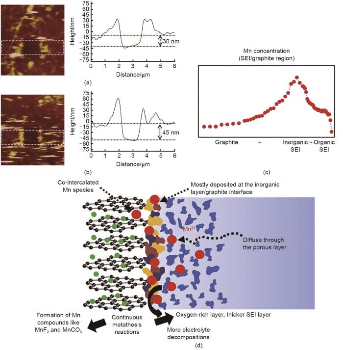
AFM height images and their corresponding averaged cross-section of HOPG cycled in (a) Mn-free electrolyte and (b) Mn-containing electrolyte; (c) Mn distribution along the cross-sectional electrode when it was stored for one month after 5 cycles in Mn-containing electrolyte; (d) Schematic diagram of the effect of Mn2+ deposition on graphite anode[54]
图6
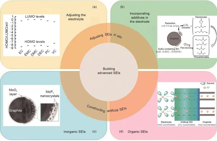
SEI膜调控策略总结 (a) 调控电解液组分,例如调节碳酸酯HOMO-LUMO的相对大小[5];(b) 在负极电极内引入添加剂,例如通过硫的添加,原位构建具有高Li+ 导电性的SEI膜[57];(c) 无机包覆层,例如MoO x -MoP x 包覆石墨的示意图[58];(d) 有机包覆层,促进Li+ 在电解质和石墨负极之间传输的聚合物SEI膜[4, 59]
Fig. 6
Summary of SEI regulation strategies (a) regulating the composition of the electrolyte, such as adjusting the HOMO-LUMO of solvents[5]; (b) Incorporating additives into the anode facilitating the in-situ construction of SEI with high Li+ conductivity, such as sulfur element[57]; (c) Inorganic coating layer, such as MoO x -MoP x coated graphite[58]; (d) Organic coating layer, such as the polymer SEI that promotes the transport of Li+ between electrolyte and graphite anode[4, 59]
Fig. 7
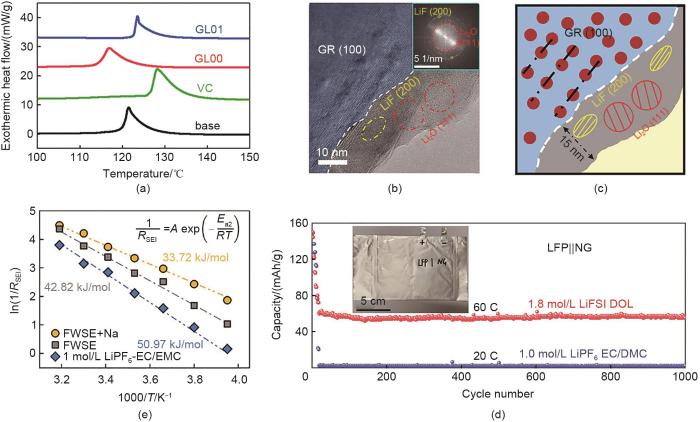
(a) DSC curves of the fully de-lithiated graphite anodes collected from the cells cycled in 1 mol/L LiPF6 EC/EMC (volume ratio 1∶2) electrolytes with/without mass fraction 2% VC/glycolide (GL00)/GL01 additives[61]; (b) High-resolution cryo-TEM image of the SEI formed in 1.8 mol/L LiFSI DOL electrolyte, and the inset shows the corresponding FFT pattern; (c) Corresponding schematic of the high-resolution cryo-TEM image; (d) Long cycling performance of LiFePO4||graphite pouch cells with two electrolytes, and the inset shows a photograph of the pouch cell[66]; (e) Diffusion activation energy of Li+ in SEI[67]
除了可溶于电解液的添加剂,还可以在石墨电极的制备过程中加入一些微溶性添加剂,通过在循环过程中缓慢释放在电解液中来影响SEI膜结构和组分[图6(b)],这也是一种原位调控SEI膜的方法。例如,Jurng等[57]在石墨电极中添加单质硫。硫在第1次锂化过程中被还原为多硫化锂,溶解在电解液中并与碳酸酯基电解液反应形成硫代碳酸酯,获得富含硫的SEI膜,有利于降低Li+在低温下的电荷转移阻抗。Qi等[68]将少量LiNO3添加到石墨电极中,并在循环过程中使其缓慢释放,在石墨表面形成含有Li3N和LiN x O y 的SEI膜,可以抑制电解液的进一步分解并促进Li+快速迁移。此外,仅包覆在石墨表面的添加剂也能够诱导形成具有特定功能的SEI膜[69]。Heng等[70]在轻度氧化的石墨表面包覆了4-乙烯苯甲酸(4-VBA)纳米层,使其原位转化为坚固、稳定的SEI膜,有效抑制了电解液的分解和SEI膜的持续生成。在负极电极内引入添加剂拓展了可使用添加剂的种类,为原位调控SEI膜提供了新的思路和方法。
通过化学气相沉积(CVD)或热气相沉积(TVD)可以在石墨表面均匀包覆非晶碳层。该碳包覆层可以一定程度抑制在高温下锂从锂化石墨中的析出,从而提高石墨电极的热稳定性[71-72]。此外,部分无机涂层具有较高的Li+电导率,有利于促进Li+在界面传输并抑制锂沉积。例如,Lee等[58]在石墨表面构建了MoO x -MoP x 双相人工SEI膜[图6(c)],其中MoP x 能够促进Li+嵌入石墨的界面动力学,抑制高倍率充电时的锂沉积;MoO x 减缓了石墨表面SEI膜的生长,两者协同作用使Li+脱溶剂化并通过SEI膜迁移的活化能显著降低。除该材料外,纳米硅[73]、Li4Ti5O12[74]和TiO2-x[75]等涂层具有相似的工作原理,有利于提高Li+界面输运,抑制锂沉积,提高LIBs的安全性。
3.2.2 有机涂层
与上述无机涂层类似,利用有机物构建人工SEI膜也是目前研究的热点之一。例如,将聚乙二醇四辛基苯醚[PEGPE; C14H22O(C2H4O) n, n=9~10]用作人工SEI膜,聚醚层中的聚合物链通过醚基氧原子与Li+配位,而聚合物的苯环通过p-p相互作用与石墨表面紧密结合。如图6(d)所示,该人工SEI膜可以使Li+由“湿”配位态向“干”配位态逐步过渡,并最终进入非配位态,从而实现Li+在电解液/石墨界面上的高效传输[59]。综上,人工SEI膜的合理设计与制备能够有效抑制LIBs的不安全因素。
WANG Q S, MAO B B, STOLIAROV S I, et al. A review of lithium ion battery failure mechanisms and fire prevention strategies[J]. Progress in Energy and Combustion Science, 2019, 73: 95-131.
ALI RAJAEIFAR M, GHADIMI P, RAUGEI M, et al. Challenges and recent developments in supply and value chains of electric vehicle batteries: A sustainability perspective[J]. Resources, Conservation and Recycling, 2022, 180: 106144.
LI W F, WANG H W, OUYANG M G, et al. Theoretical and experimental analysis of the lithium-ion battery thermal runaway process based on the internal combustion engine combustion theory[J]. Energy Conversion and Management, 2019, 185: 211-222.
JIANG X M, CHEN Y J, MENG X K, et al. The impact of electrode with carbon materials on safety performance of lithium-ion batteries: A review[J]. Carbon, 2022, 191: 448-470.
LEI B X, ZHAO W J, ZIEBERT C, et al. Experimental analysis of thermal runaway in 18650 cylindrical Li-ion cells using an accelerating rate calorimeter[J]. Batteries, 2017, 3(4): 14.
WANG M, NOELLE D J, SHI Y, et al. Effect of Notch depth of modified current collector on internal-short-circuit mitigation for lithium-ion battery[J]. Journal of Physics D: Applied Physics, 2018, 51(1): 015502.
FENG X N, OUYANG M G, LIU X, et al. Thermal runaway mechanism of lithium ion battery for electric vehicles: A review[J]. Energy Storage Materials, 2018, 10: 246-267.
LI Y Q, LU Y X, ADELHELM P, et al. Intercalation chemistry of graphite: Alkali metal ions and beyond[J]. Chemical Society Reviews, 2019, 48(17): 4655-4687.
ETACHERI V, MAROM R, ELAZARI R, et al. Challenges in the development of advanced Li-ion batteries: A review[J]. Energy & Environmental Science, 2011, 4(9): 3243-3262.
AURBACH D, MARKOVSKY B, SHECHTER A, et al. A comparative study of synthetic graphite and Li electrodes in electrolyte solutions based on ethylene carbonate-dimethyl carbonate mixtures[J]. Journal of the Electrochemical Society, 1996, 143(12): 3809-3820.
VERMA P, MAIRE P, NOVÁK P. A review of the features and analyses of the solid electrolyte interphase in Li-ion batteries[J]. Electrochimica Acta, 2010, 55(22): 6332-6341.
PELED E, MENKIN S. Review—SEI: Past, present and future[J]. Journal of the Electrochemical Society, 2017, 164(7): A1703-A1719.
XU K. Electrolytes and interphases in Li-ion batteries and beyond[J]. Chemical Reviews, 2014, 114(23): 11503-11618.
AN S J, LI J L, DANIEL C, et al. The state of understanding of the lithium-ion-battery graphite solid electrolyte interphase (SEI) and its relationship to formation cycling[J]. Carbon, 2016, 105: 52-76.
YUAN S Y, WENG S T, WANG F, et al. Revisiting the designing criteria of advanced solid electrolyte interphase on lithium metal anode under practical condition[J]. Nano Energy, 2021, 83: doi: 10. 1016/j. nanoen. 2021. 105847.
HEISKANEN S K, KIM J, LUCHT B L. Generation and evolution of the solid electrolyte interphase of lithium-ion batteries[J]. Joule, 2019, 3(10): 2322-2333.
NIE M Y, CHALASANI D, ABRAHAM D P, et al. Lithium ion battery graphite solid electrolyte interphase revealed by microscopy and spectroscopy[J]. The Journal of Physical Chemistry C, 2013, 117(3): 1257-1267.
YOON T, MILIEN M S, PARIMALAM B S, et al. Thermal decomposition of the solid electrolyte interphase (SEI) on silicon electrodes for lithium ion batteries[J]. Chemistry of Materials, 2017, 29(7): 3237-3245.
ZENG X J, LIU D Q, WANG S W, et al. Insitu observation of interface evolution on a graphite anode by scanning electrochemical microscopy[J]. ACS Applied Materials & Interfaces, 2020, 12(33): 37047-37053.
SHI S Q, LU P, LIU Z Y, et al. Direct calculation of Li-ion transport in the solid electrolyte interphase[J]. Journal of the American Chemical Society, 2012, 134(37): 15476-15487.
BENITEZ L, SEMINARIO J M. Ion diffusivity through the solid electrolyte interphase in lithium-ion batteries[J]. Journal of the Electrochemical Society, 2017, 164(11): E3159-E3170.
RAMASUBRAMANIAN A, YURKIV V, FOROOZAN T, et al. Lithium diffusion mechanism through solid-electrolyte interphase in rechargeable lithium batteries[J]. The Journal of Physical Chemistry C, 2019, 123(16): 10237-10245.
PELJO P, GIRAULT H H. Electrochemical potential window of battery electrolytes: The HOMO-LUMO misconception[J]. Energy & Environmental Science, 2018, 11(9): 2306-2309.
ZHANG H M, WANG J, WANG Y B, et al. Multiscale modeling of the SEI of lithium-ion batteries[J]. Energy Storage Science and Technology, 2023, 12(2): 366-382.
FENG X N, ZHENG S Q, REN D S, et al. Investigating the thermal runaway mechanisms of lithium-ion batteries based on thermal analysis database[J]. Applied Energy, 2019, 246: 53-64.
HUANG S Q, CHEONG L Z, WANG D Y, et al. Thermal stability of solid electrolyte interphase of lithium-ion batteries[J]. Applied Surface Science, 2018, 454: 61-67.
PARIMALAM B S, MACINTOSH A D, KADAM R, et al. Decomposition reactions of anode solid electrolyte interphase (SEI) components with LiPF6[J]. The Journal of Physical Chemistry C, 2017, 121(41): 22733-22738.
SEO D M, CHALASANI D, PARIMALAM B S, et al. Reduction reactions of carbonate solvents for lithium ion batteries[J]. ECS Electrochemistry Letters, 2014, 3(9): A91-A93.
LIU X, YIN L, REN D S, et al. Insitu observation of thermal-driven degradation and safety concerns of lithiated graphite anode[J]. Nature Communications, 2021, 12: 4235.
KRISTON A, ADANOUJ I, RUIZ V, et al. Quantification and simulation of thermal decomposition reactions of Li-ion battery materials by simultaneous thermal analysis coupled with gas analysis[J]. Journal of Power Sources, 2019, 435(30): 226774.
XU K, ZHUANG G V, ALLEN J L, et al. Syntheses and characterization of lithium alkyl mono-and dicarbonates as components of surface films in Li-ion batteries[J]. The Journal of Physical Chemistry B, 2006, 110(15): 7708-7719.
GAO Q, ZHAO J, LI G. Research progress of fast-chaiging lithium-ion batteries[J/OL]. Energy Storage Science and Technology: 1-18[2023-06-27]. https: //doi.org/10.19799/j.cnki.2095-4239.2023-0287.
ZHAO X C, YIN Y L, HU Y, et al. Electrochemical-thermal modeling of lithium plating/stripping of Li(Ni0.6Mn0.2Co0.2)O2/carbon lithium-ion batteries at subzero ambient temperatures[J]. Journal of Power Sources, 2019, 418: 61-73.
BIRKENMAIER C, BITZER B, HARZHEIM M, et al. Lithium plating on graphite negative electrodes: Innovative qualitative and quantitative investigation methods[J]. Journal of the Electrochemical Society, 2015, 162(14): A2646-A2650.
WALDMANN T, HOGG B I, WOHLFAHRT-MEHRENS M. Li plating as unwanted side reaction in commercial Li-ion cells-A review[J]. Journal of Power Sources, 2018, 384: 107-124.
YANG G J, ZHANG S M, WENG S T, et al. Anionic effect on enhancing the stability of a solid electrolyte interphase film for lithium deposition on graphite[J]. Nano Letters, 2021, 21(12): 5316-5323.
LIN D C, LIU Y Y, CUI Y. Reviving the lithium metal anode for high-energy batteries[J]. Nature Nanotechnology, 2017, 12(3): 194-206.
HAO F, VERMA A, MUKHERJEE P P. Mechanistic insight into dendrite-SEI interactions for lithium metal electrodes[J]. Journal of Materials Chemistry A, 2018, 6(40): 19664-19671.
YAN C, ZHANG Q A. Towards the intercalation and lithium plating mechanism for high safety and fast-charging lithium-ion batteries: A review[J]. Energy Lab, 2022, 1: 220011.
ABRAHAM D P, SPILA T, FURCZON M M, et al. Evidence of transition-metal accumulation on aged graphite anodes by SIMS[J]. Electrochemical and Solid-State Letters, 2008, 11(12): A226.
SHIN H, PARK J, SASTRY A M, et al. Degradation of the solid electrolyte interphase induced by the deposition of manganese ions[J]. Journal of Power Sources, 2015, 284: 416-427.
LI W D, KIM U H, DOLOCAN A, et al. Formation and inhibition of metallic lithium microstructures in lithium batteries driven by chemical crossover[J]. ACS Nano, 2017, 11(6): 5853-5863.
XIE Q M, CHEN J W, XING L D, et al. Revealing the critical effect of solid electrolyte interphase on the deposition and detriment of Co(Ⅱ) ions to graphite anode[J]. Journal of Energy Chemistry, 2022, 69: 389-396.
JURNG S, KIM H S, LEE J G, et al. Low-temperature characteristics and film-forming mechanism of elemental sulfur additive on graphite negative electrode[J]. Journal of the Electrochemical Society, 2015, 163(2): A223-A228.
LEE S M, KIM J, MOON J, et al. A cooperative biphasic MoOx-MoPx promoter enables a fast-charging lithium-ion battery[J]. Nature Communications, 2021, 12: 39.
LI F S, WU Y S, CHOU J, et al. A mechanically robust and highly ion-conductive polymer-blend coating for high-power and long-life lithium-ion battery anodes[J]. Advanced Materials, 2015, 27(1): 130-137.
OTA H, SAKATA Y, INOUE A, et al. Analysis of vinylene carbonate derived SEI layers on graphite anode[J]. Journal of the Electrochemical Society, 2004, 151(10): A1659.
JEON J, YOON S, PARK T, et al. Tuning glycolide as an SEI-forming additive for thermally robust Li-ion batteries[J]. Journal of Materials Chemistry, 2012, 22(39): 21003-21008.
ESHETU G G, GRUGEON S, GACHOT G, et al. LiFSI vs. LiPF6 electrolytes in contact with lithiated graphite: Comparing thermal stabilities and identification of specific SEI-reinforcing additives[J]. Electrochimica Acta, 2013, 102: 133-141.
TAN J A, MATZ J, DONG P, et al. A growing appreciation for the role of LiF in the solid electrolyte interphase[J]. Advanced Energy Materials, 2021, 11(16): 2100046.
JIANG H, LIU J E, WANG M M, et al. Stable rooted solid electrolyte interphase for lithium-ion batteries[J]. The Journal of Physical Chemistry Letters, 2021, 12(43): 10521-10531.
HE M F, GUO R, HOBOLD G M, et al. The intrinsic behavior of lithium fluoride in solid electrolyte interphases on lithium[J]. Proceedings of the National Academy of Sciences of the United States of America, 2020, 117(1): 73-79.
ZHENG X Y, CAO Z, LUO W, et al. Solvation and interfacial engineering enable -40 ℃ operation of graphite/NCM batteries at energy density over 270 Wh/kg[J]. Advanced Materials, 2023, 35(10): e2210115.
QI W B, BEN L B, YU H L, et al. Improving the electrochemical cycling performance of anode materials via facile insitu surface deposition of a solid electrolyte layer[J]. Journal of Power Sources, 2019, 424: 150-157.
HENG S A, CAO Z, WANG Y, et al. Insitu transformed solid electrolyte interphase by implanting a 4-vinylbenzoic acid nanolayer on the natural graphite surface[J]. ACS Applied Materials & Interfaces, 2020, 12(29): 33408-33420.
LI H Q, ZHOU H S. Enhancing the performances of Li-ion batteries by carbon-coating: Present and future[J]. Chemical Communications, 2012, 48(9): 1201-1217.
NATARAJAN C, FUJIMOTO H, TOKUMITSU K, et al. Reduction of the irreversible capacity of a graphite anode by the CVD process[J]. Carbon, 2001, 39(9): 1409-1413.
KIM N, CHAE S, MA J, et al. Fast-charging high-energy lithium-ion batteries via implantation of amorphous silicon nanolayer in edge-plane activated graphite anodes[J]. Nature Communications, 2017, 8: 812.
SONG D, JO M R, LEE G H, et al. Bifunctional Li4Ti5O12 coating layer for the enhanced kinetics and stability of carbon anode for lithium rechargeable batteries[J]. Journal of Alloys and Compounds, 2014, 615: 220-226.
KIM D S, CHUNG D J, BAE J, et al. Surface engineering of graphite anode material with black TiO2-x for fast chargeable lithium ion battery[J]. Electrochimica Acta, 2017, 258: 336-342.
... 如图4(a)所示,锂沉积发生在局部电位低于0 V (vs. Li+/Li)时,而Li+嵌入石墨的电位高于此值(约0.1 V vs. Li+/Li);因此,在热力学上,锂嵌入石墨要优先于锂沉积发生[46].然而,在实际应用的全电池中,尤其在快充、低温和长循环条件下,由于欧姆电位降、浓差过电势、电荷转移过电势等多种极化效应将负极电位降低至锂沉积阈值.在微观层面上[图4(b)],锂沉积和锂插层共存在于全电池充电过程中,表达式分别为[47]:
(a) Macroscopic and (b) microscopic mechanisms of lithium plating during Li<sup>+</sup> intercalation into graphite<sup>[<xref ref-type="bibr" rid="R4">4</xref>]</sup>; (c) Effect of lithium plating on SEI<sup>[<xref ref-type="bibr" rid="R45">45</xref>]</sup>Fig. 4xLi++Li δ C6+xe-→Li δ+x C6Li++e-→Li
Summary of SEI regulation strategies (a) regulating the composition of the electrolyte, such as adjusting the HOMO-LUMO of solvents<sup>[<xref ref-type="bibr" rid="R5">5</xref>]</sup>; (b) Incorporating additives into the anode facilitating the <i>in-situ</i> construction of SEI with high Li<sup>+</sup> conductivity, such as sulfur element<sup>[<xref ref-type="bibr" rid="R57">57</xref>]</sup>; (c) Inorganic coating layer, such as MoO <i><sub>x</sub></i> -MoP <i><sub>x</sub></i> coated graphite<sup>[<xref ref-type="bibr" rid="R58">58</xref>]</sup>; (d) Organic coating layer, such as the polymer SEI that promotes the transport of Li<sup>+</sup> between electrolyte and graphite anode<sup>[<xref ref-type="bibr" rid="R4">4</xref>, <xref ref-type="bibr" rid="R59">59</xref>]</sup>Fig. 6<strong>3.1</strong> <strong>SEI</strong>膜的原位调控
<strong>(a) Schematic of SEI formation on graphite anode</strong><sup>[<xref ref-type="bibr" rid="R22">22</xref>]</sup><strong>; (b) Thermodynamics of SEI formation on anode and cathode, where <i>μ</i><sub>e</sub></strong><sub>-</sub><strong><sub>,Anode</sub> and <i>μ</i><sub>e</sub></strong><sub>-</sub><strong><sub>,Cathode</sub> are the electrochemical potentials of the anode and cathode respectively, and the stability window of the electrolyte is the difference between the energies of LUMO and HOMO, expressed as <i>E</i><sub>g</sub></strong><sup>[<xref ref-type="bibr" rid="R30">30</xref>]</sup><strong>; (c) Qualitative description of chain reactions during thermal runaway</strong><sup>[<xref ref-type="bibr" rid="R5">5</xref>]</sup>Fig. 1<strong>1.2</strong> 形成热力学
Summary of SEI regulation strategies (a) regulating the composition of the electrolyte, such as adjusting the HOMO-LUMO of solvents<sup>[<xref ref-type="bibr" rid="R5">5</xref>]</sup>; (b) Incorporating additives into the anode facilitating the <i>in-situ</i> construction of SEI with high Li<sup>+</sup> conductivity, such as sulfur element<sup>[<xref ref-type="bibr" rid="R57">57</xref>]</sup>; (c) Inorganic coating layer, such as MoO <i><sub>x</sub></i> -MoP <i><sub>x</sub></i> coated graphite<sup>[<xref ref-type="bibr" rid="R58">58</xref>]</sup>; (d) Organic coating layer, such as the polymer SEI that promotes the transport of Li<sup>+</sup> between electrolyte and graphite anode<sup>[<xref ref-type="bibr" rid="R4">4</xref>, <xref ref-type="bibr" rid="R59">59</xref>]</sup>Fig. 6<strong>3.1</strong> <strong>SEI</strong>膜的原位调控
... [5]; (b) Incorporating additives into the anode facilitating the in-situ construction of SEI with high Li+ conductivity, such as sulfur element[57]; (c) Inorganic coating layer, such as MoO x -MoP x coated graphite[58]; (d) Organic coating layer, such as the polymer SEI that promotes the transport of Li+ between electrolyte and graphite anode[4, 59]Fig. 6<strong>3.1</strong> <strong>SEI</strong>膜的原位调控
... 锂离子电池(LIBs)因其在高效储能和环境友好[1]方面的巨大潜力而逐渐成为全球电能存储的主流,投放市场的电池容量和数量在近年来出现了惊人的增长[2].据统计,LIBs装机总容量已从2010年的29.6 GWh增长至2022年的750 GWh,预计到2030年将突破2500 GWh[3].然而,随着LIBs的快速普及和电动汽车[4]、智能电网[5]等的推广和应用,在能量密度、倍率性能、循环寿命、成本和安全性能等各个方面对LIBs提出了更高的要求.然而,目前LIBs的安全性能还不够理想.据统计,新能源电动车燃烧事故中,约60%来自三元LIBs.2011—2021年间,全球共报道32起储能电站起火爆炸事故,其中25起与LIBs相关.Samsung Note7手机爆炸和Tesla Model S起火等事件,不仅对人们的生命财产造成了极大的威胁,而且对LIBs产业产生了巨大冲击[6-7].热失控是LIBs失效引发安全事故的重要形式之一[6, 8-9].电池内部温度升高会引发一系列放热反应;热量在电池内部积累,进一步加快了反应速率,造成温度急剧升高、产生可燃气体并破坏电池内部结构,甚至导致火灾或爆炸[9].此外,电池内部发生短路也会造成电池温度急剧升高[10-11]. ...
3
... 锂离子电池(LIBs)因其在高效储能和环境友好[1]方面的巨大潜力而逐渐成为全球电能存储的主流,投放市场的电池容量和数量在近年来出现了惊人的增长[2].据统计,LIBs装机总容量已从2010年的29.6 GWh增长至2022年的750 GWh,预计到2030年将突破2500 GWh[3].然而,随着LIBs的快速普及和电动汽车[4]、智能电网[5]等的推广和应用,在能量密度、倍率性能、循环寿命、成本和安全性能等各个方面对LIBs提出了更高的要求.然而,目前LIBs的安全性能还不够理想.据统计,新能源电动车燃烧事故中,约60%来自三元LIBs.2011—2021年间,全球共报道32起储能电站起火爆炸事故,其中25起与LIBs相关.Samsung Note7手机爆炸和Tesla Model S起火等事件,不仅对人们的生命财产造成了极大的威胁,而且对LIBs产业产生了巨大冲击[6-7].热失控是LIBs失效引发安全事故的重要形式之一[6, 8-9].电池内部温度升高会引发一系列放热反应;热量在电池内部积累,进一步加快了反应速率,造成温度急剧升高、产生可燃气体并破坏电池内部结构,甚至导致火灾或爆炸[9].此外,电池内部发生短路也会造成电池温度急剧升高[10-11]. ...
... LIBs的热失控并非单一因素所致,而更像是多米诺骨牌,由一系列连锁反应组成,其中固体电解质界面(SEI)膜的分解位于这些反应的起始位置[12].因此,通过调控SEI膜来抑制或延缓热失控过程成为一种顺理成章的思路和方法.近年来,随着表征技术的不断进步,人们逐渐加深了对SEI膜的认识,在调控SEI膜来提升电池安全性方面也积累了不少经验.此外,研究表明,负极材料是电池内形成SEI膜的主要位置[8].石墨凭借其高容量(372 mAh/g)、低工作电位(约0.1 V vs. Li+/Li)、低成本和长循环寿命[13-14],自20世纪90年代初至今始终作为商用LIBs的主要负极材料之一,也是未来不可完全替代的关键负极之一.鉴于此,以石墨负极为研究对象,系统介绍SEI膜的生成、分解与调控,及其与电池热失控之间的关系. ...
... 锂离子电池(LIBs)因其在高效储能和环境友好[1]方面的巨大潜力而逐渐成为全球电能存储的主流,投放市场的电池容量和数量在近年来出现了惊人的增长[2].据统计,LIBs装机总容量已从2010年的29.6 GWh增长至2022年的750 GWh,预计到2030年将突破2500 GWh[3].然而,随着LIBs的快速普及和电动汽车[4]、智能电网[5]等的推广和应用,在能量密度、倍率性能、循环寿命、成本和安全性能等各个方面对LIBs提出了更高的要求.然而,目前LIBs的安全性能还不够理想.据统计,新能源电动车燃烧事故中,约60%来自三元LIBs.2011—2021年间,全球共报道32起储能电站起火爆炸事故,其中25起与LIBs相关.Samsung Note7手机爆炸和Tesla Model S起火等事件,不仅对人们的生命财产造成了极大的威胁,而且对LIBs产业产生了巨大冲击[6-7].热失控是LIBs失效引发安全事故的重要形式之一[6, 8-9].电池内部温度升高会引发一系列放热反应;热量在电池内部积累,进一步加快了反应速率,造成温度急剧升高、产生可燃气体并破坏电池内部结构,甚至导致火灾或爆炸[9].此外,电池内部发生短路也会造成电池温度急剧升高[10-11]. ...
... [9].此外,电池内部发生短路也会造成电池温度急剧升高[10-11]. ...
1
... 锂离子电池(LIBs)因其在高效储能和环境友好[1]方面的巨大潜力而逐渐成为全球电能存储的主流,投放市场的电池容量和数量在近年来出现了惊人的增长[2].据统计,LIBs装机总容量已从2010年的29.6 GWh增长至2022年的750 GWh,预计到2030年将突破2500 GWh[3].然而,随着LIBs的快速普及和电动汽车[4]、智能电网[5]等的推广和应用,在能量密度、倍率性能、循环寿命、成本和安全性能等各个方面对LIBs提出了更高的要求.然而,目前LIBs的安全性能还不够理想.据统计,新能源电动车燃烧事故中,约60%来自三元LIBs.2011—2021年间,全球共报道32起储能电站起火爆炸事故,其中25起与LIBs相关.Samsung Note7手机爆炸和Tesla Model S起火等事件,不仅对人们的生命财产造成了极大的威胁,而且对LIBs产业产生了巨大冲击[6-7].热失控是LIBs失效引发安全事故的重要形式之一[6, 8-9].电池内部温度升高会引发一系列放热反应;热量在电池内部积累,进一步加快了反应速率,造成温度急剧升高、产生可燃气体并破坏电池内部结构,甚至导致火灾或爆炸[9].此外,电池内部发生短路也会造成电池温度急剧升高[10-11]. ...
2
... LIBs的热失控并非单一因素所致,而更像是多米诺骨牌,由一系列连锁反应组成,其中固体电解质界面(SEI)膜的分解位于这些反应的起始位置[12].因此,通过调控SEI膜来抑制或延缓热失控过程成为一种顺理成章的思路和方法.近年来,随着表征技术的不断进步,人们逐渐加深了对SEI膜的认识,在调控SEI膜来提升电池安全性方面也积累了不少经验.此外,研究表明,负极材料是电池内形成SEI膜的主要位置[8].石墨凭借其高容量(372 mAh/g)、低工作电位(约0.1 V vs. Li+/Li)、低成本和长循环寿命[13-14],自20世纪90年代初至今始终作为商用LIBs的主要负极材料之一,也是未来不可完全替代的关键负极之一.鉴于此,以石墨负极为研究对象,系统介绍SEI膜的生成、分解与调控,及其与电池热失控之间的关系. ...
... LIBs的热失控并非单一因素所致,而更像是多米诺骨牌,由一系列连锁反应组成,其中固体电解质界面(SEI)膜的分解位于这些反应的起始位置[12].因此,通过调控SEI膜来抑制或延缓热失控过程成为一种顺理成章的思路和方法.近年来,随着表征技术的不断进步,人们逐渐加深了对SEI膜的认识,在调控SEI膜来提升电池安全性方面也积累了不少经验.此外,研究表明,负极材料是电池内形成SEI膜的主要位置[8].石墨凭借其高容量(372 mAh/g)、低工作电位(约0.1 V vs. Li+/Li)、低成本和长循环寿命[13-14],自20世纪90年代初至今始终作为商用LIBs的主要负极材料之一,也是未来不可完全替代的关键负极之一.鉴于此,以石墨负极为研究对象,系统介绍SEI膜的生成、分解与调控,及其与电池热失控之间的关系. ...
1
... LIBs的热失控并非单一因素所致,而更像是多米诺骨牌,由一系列连锁反应组成,其中固体电解质界面(SEI)膜的分解位于这些反应的起始位置[12].因此,通过调控SEI膜来抑制或延缓热失控过程成为一种顺理成章的思路和方法.近年来,随着表征技术的不断进步,人们逐渐加深了对SEI膜的认识,在调控SEI膜来提升电池安全性方面也积累了不少经验.此外,研究表明,负极材料是电池内形成SEI膜的主要位置[8].石墨凭借其高容量(372 mAh/g)、低工作电位(约0.1 V vs. Li+/Li)、低成本和长循环寿命[13-14],自20世纪90年代初至今始终作为商用LIBs的主要负极材料之一,也是未来不可完全替代的关键负极之一.鉴于此,以石墨负极为研究对象,系统介绍SEI膜的生成、分解与调控,及其与电池热失控之间的关系. ...
... 由SEI膜的形成机制可知,其物质组成与所用电解液的类型和分解路径直接相关[20-21].商用LIBs电解液一般由LiPF6溶解于有机碳酸酯混合溶剂构成,包括环状碳酸酯(如碳酸乙烯酯EC)和链状碳酸酯(如碳酸二甲酯DMC、碳酸二乙酯DEC和碳酸甲乙酯EMC).与链状碳酸酯相比,EC更容易发生还原分解[22].因此,SEI膜的主要成分是由EC还原生成的二碳酸乙烯锂(LEDC)和LiPF6生成的LiF和Li x PO y F z[23-24],反应如下: ...
... 由SEI膜的形成机制可知,其物质组成与所用电解液的类型和分解路径直接相关[20-21].商用LIBs电解液一般由LiPF6溶解于有机碳酸酯混合溶剂构成,包括环状碳酸酯(如碳酸乙烯酯EC)和链状碳酸酯(如碳酸二甲酯DMC、碳酸二乙酯DEC和碳酸甲乙酯EMC).与链状碳酸酯相比,EC更容易发生还原分解[22].因此,SEI膜的主要成分是由EC还原生成的二碳酸乙烯锂(LEDC)和LiPF6生成的LiF和Li x PO y F z[23-24],反应如下: ...
5
... 由SEI膜的形成机制可知,其物质组成与所用电解液的类型和分解路径直接相关[20-21].商用LIBs电解液一般由LiPF6溶解于有机碳酸酯混合溶剂构成,包括环状碳酸酯(如碳酸乙烯酯EC)和链状碳酸酯(如碳酸二甲酯DMC、碳酸二乙酯DEC和碳酸甲乙酯EMC).与链状碳酸酯相比,EC更容易发生还原分解[22].因此,SEI膜的主要成分是由EC还原生成的二碳酸乙烯锂(LEDC)和LiPF6生成的LiF和Li x PO y F z[23-24],反应如下: ...
... [22];(b) 正负极SEI膜的形成热力学,其中 μe-,Anode 和 μe-,Cathode 分别为负极和正极的电化学势,电解质的稳定窗口是LUMO和HOMO的能量之差,表示为 Eg[30];(c) 定性描述热失控过程中的连锁反应[5]<strong>(a) Schematic of SEI formation on graphite anode</strong><sup>[<xref ref-type="bibr" rid="R22">22</xref>]</sup><strong>; (b) Thermodynamics of SEI formation on anode and cathode, where <i>μ</i><sub>e</sub></strong><sub>-</sub><strong><sub>,Anode</sub> and <i>μ</i><sub>e</sub></strong><sub>-</sub><strong><sub>,Cathode</sub> are the electrochemical potentials of the anode and cathode respectively, and the stability window of the electrolyte is the difference between the energies of LUMO and HOMO, expressed as <i>E</i><sub>g</sub></strong><sup>[<xref ref-type="bibr" rid="R30">30</xref>]</sup><strong>; (c) Qualitative description of chain reactions during thermal runaway</strong><sup>[<xref ref-type="bibr" rid="R5">5</xref>]</sup>Fig. 1<strong>1.2</strong> 形成热力学
... [22]; (b) Thermodynamics of SEI formation on anode and cathode, where μe-,Anode and μe-,Cathode are the electrochemical potentials of the anode and cathode respectively, and the stability window of the electrolyte is the difference between the energies of LUMO and HOMO, expressed as Eg[30]; (c) Qualitative description of chain reactions during thermal runaway[5]Fig. 1<strong>1.2</strong> 形成热力学
... 由SEI膜的形成机制可知,其物质组成与所用电解液的类型和分解路径直接相关[20-21].商用LIBs电解液一般由LiPF6溶解于有机碳酸酯混合溶剂构成,包括环状碳酸酯(如碳酸乙烯酯EC)和链状碳酸酯(如碳酸二甲酯DMC、碳酸二乙酯DEC和碳酸甲乙酯EMC).与链状碳酸酯相比,EC更容易发生还原分解[22].因此,SEI膜的主要成分是由EC还原生成的二碳酸乙烯锂(LEDC)和LiPF6生成的LiF和Li x PO y F z[23-24],反应如下: ...
1
... 由SEI膜的形成机制可知,其物质组成与所用电解液的类型和分解路径直接相关[20-21].商用LIBs电解液一般由LiPF6溶解于有机碳酸酯混合溶剂构成,包括环状碳酸酯(如碳酸乙烯酯EC)和链状碳酸酯(如碳酸二甲酯DMC、碳酸二乙酯DEC和碳酸甲乙酯EMC).与链状碳酸酯相比,EC更容易发生还原分解[22].因此,SEI膜的主要成分是由EC还原生成的二碳酸乙烯锂(LEDC)和LiPF6生成的LiF和Li x PO y F z[23-24],反应如下: ...
<strong>(a) Schematic of SEI formation on graphite anode</strong><sup>[<xref ref-type="bibr" rid="R22">22</xref>]</sup><strong>; (b) Thermodynamics of SEI formation on anode and cathode, where <i>μ</i><sub>e</sub></strong><sub>-</sub><strong><sub>,Anode</sub> and <i>μ</i><sub>e</sub></strong><sub>-</sub><strong><sub>,Cathode</sub> are the electrochemical potentials of the anode and cathode respectively, and the stability window of the electrolyte is the difference between the energies of LUMO and HOMO, expressed as <i>E</i><sub>g</sub></strong><sup>[<xref ref-type="bibr" rid="R30">30</xref>]</sup><strong>; (c) Qualitative description of chain reactions during thermal runaway</strong><sup>[<xref ref-type="bibr" rid="R5">5</xref>]</sup>Fig. 1<strong>1.2</strong> 形成热力学
... SEI膜的热分解作为热失控过程的第1步,需要充分了解它的分解过程.Wu等[34]利用原位加热X射线光电子能谱(XPS)和低温透射电子显微镜(cryo-TEM)等表征手段,原位和非原位地监测具有类石墨结构的气相生长碳纤维(VGCF)表面SEI膜的热分解过程(图2).如图2(a)所示,采用特殊设计的载物台可以允许使用XPS原位监测样品在加热过程中的成分演变.根据对XPS谱的定量分析发现[图2(b)],SEI膜中的部分有机物在25~50 ℃较低温度下已经开始发生分解,形成Li2O、LiF和Li2CO3等无机物.在持续加热过程中,无机化合物中的C和O含量不断增加而有机化合物中的C和O相应逐渐减少;LiF含量增加而Li x PO y F z 含量显著降低;这说明有机物和Li x PO y F z 均发生了分解.其中Li x PO y F z 在200~250 ℃时发生完全分解,对应反应为: ...
... [34]<strong>(a) Schematic of <i>in-situ</i> heating XPS; (b) Quantitative analysis of the XPS survey spectra, C 1s, O 1s, and F 1s spectra from the lithiated VGCF during the temperature rising from 25</strong> ℃ <strong>to 300</strong> ℃<strong>; (c) Cryo-TEM images of SEI on the lithiated VGCF at 25, 150, 200</strong> ℃ <strong>and their corresponding elemental distribution of C (marked in red) and O (marked in green) based on EELS map scanning</strong><sup>[<xref ref-type="bibr" rid="R34">34</xref>]</sup>Fig. 2Li x PO y F z →LiF+Li x-z PO y
... SEI膜分解放热导致电池内温度上升,会引发锂化石墨发生热解.Liu等[39]利用同步辐射X射线衍射技术(XRD)原位研究了锂化石墨在加热过程中的结构变化.如图3(a)所示,晶面间距d的变化揭示了LiC6→LiC12→LiC18→石墨的相变规律.在40 ℃时,LiC6的XRD峰强度开始随着LiC12的增大而降低,此时SEI膜中PEO等低聚物开始发生分解.当温度达到约120和170 ℃,LiC6和LiC12相继消失,转变为LiC18;在约250 ℃时,LiC18相逐渐消失,转变为2H石墨相.分别在约170和180 ℃探测到LiF和Li2O的特征衍射峰,其中LiF主要由LiC x 析出的锂与聚偏氟乙烯(PVDF)黏结剂发生反应形成[40]: ...
... [39]<strong>(a) <i>In-situ</i> XRD patterns of the lithiated graphite anode when heated from 25 to 280</strong> ℃ <strong>at 2</strong> ℃<strong>/min; (b) The influence of oxygen on the lithiated graphite anode at different temperatures during the DSC measurements; (c) <i>In-situ</i> monitoring the evolution of H<sub>2</sub>, CH<sub>3</sub>·, CH<sub>4</sub>, CO/C<sub>2</sub>H<sub>4</sub>, O<sub>2</sub>, and CO<sub>2</sub> during heating of the lithiated graphite anode; (d) The quantitative analysis of the gas cumulative ratio at 100, 150, 200, and 250</strong> ℃<strong>, respectively</strong><sup>[<xref ref-type="bibr" rid="R39">39</xref>]</sup>Fig. 3Li+(-CF2-CH2-)2 → H2(g)+LiF+(-CH=CH-CH=CH-)(约170 ℃)
... 如图4(a)所示,锂沉积发生在局部电位低于0 V (vs. Li+/Li)时,而Li+嵌入石墨的电位高于此值(约0.1 V vs. Li+/Li);因此,在热力学上,锂嵌入石墨要优先于锂沉积发生[46].然而,在实际应用的全电池中,尤其在快充、低温和长循环条件下,由于欧姆电位降、浓差过电势、电荷转移过电势等多种极化效应将负极电位降低至锂沉积阈值.在微观层面上[图4(b)],锂沉积和锂插层共存在于全电池充电过程中,表达式分别为[47]:
(a) Macroscopic and (b) microscopic mechanisms of lithium plating during Li<sup>+</sup> intercalation into graphite<sup>[<xref ref-type="bibr" rid="R4">4</xref>]</sup>; (c) Effect of lithium plating on SEI<sup>[<xref ref-type="bibr" rid="R45">45</xref>]</sup>Fig. 4xLi++Li δ C6+xe-→Li δ+x C6Li++e-→Li
... 如图4(a)所示,锂沉积发生在局部电位低于0 V (vs. Li+/Li)时,而Li+嵌入石墨的电位高于此值(约0.1 V vs. Li+/Li);因此,在热力学上,锂嵌入石墨要优先于锂沉积发生[46].然而,在实际应用的全电池中,尤其在快充、低温和长循环条件下,由于欧姆电位降、浓差过电势、电荷转移过电势等多种极化效应将负极电位降低至锂沉积阈值.在微观层面上[图4(b)],锂沉积和锂插层共存在于全电池充电过程中,表达式分别为[47]: ...
... 如图4(a)所示,锂沉积发生在局部电位低于0 V (vs. Li+/Li)时,而Li+嵌入石墨的电位高于此值(约0.1 V vs. Li+/Li);因此,在热力学上,锂嵌入石墨要优先于锂沉积发生[46].然而,在实际应用的全电池中,尤其在快充、低温和长循环条件下,由于欧姆电位降、浓差过电势、电荷转移过电势等多种极化效应将负极电位降低至锂沉积阈值.在微观层面上[图4(b)],锂沉积和锂插层共存在于全电池充电过程中,表达式分别为[47]: ...
... (11)AFM height images and their corresponding averaged cross-section of HOPG cycled in (a) Mn-free electrolyte and (b) Mn-containing electrolyte; (c) Mn distribution along the cross-sectional electrode when it was stored for one month after 5 cycles in Mn-containing electrolyte; (d) Schematic diagram of the effect of Mn<sup>2+</sup> deposition on graphite anode<sup>[<xref ref-type="bibr" rid="R54">54</xref>]</sup>Fig. 5
Summary of SEI regulation strategies (a) regulating the composition of the electrolyte, such as adjusting the HOMO-LUMO of solvents<sup>[<xref ref-type="bibr" rid="R5">5</xref>]</sup>; (b) Incorporating additives into the anode facilitating the <i>in-situ</i> construction of SEI with high Li<sup>+</sup> conductivity, such as sulfur element<sup>[<xref ref-type="bibr" rid="R57">57</xref>]</sup>; (c) Inorganic coating layer, such as MoO <i><sub>x</sub></i> -MoP <i><sub>x</sub></i> coated graphite<sup>[<xref ref-type="bibr" rid="R58">58</xref>]</sup>; (d) Organic coating layer, such as the polymer SEI that promotes the transport of Li<sup>+</sup> between electrolyte and graphite anode<sup>[<xref ref-type="bibr" rid="R4">4</xref>, <xref ref-type="bibr" rid="R59">59</xref>]</sup>Fig. 6<strong>3.1</strong> <strong>SEI</strong>膜的原位调控
... [57]; (c) Inorganic coating layer, such as MoO x -MoP x coated graphite[58]; (d) Organic coating layer, such as the polymer SEI that promotes the transport of Li+ between electrolyte and graphite anode[4, 59]Fig. 6<strong>3.1</strong> <strong>SEI</strong>膜的原位调控
... 除了可溶于电解液的添加剂,还可以在石墨电极的制备过程中加入一些微溶性添加剂,通过在循环过程中缓慢释放在电解液中来影响SEI膜结构和组分[图6(b)],这也是一种原位调控SEI膜的方法.例如,Jurng等[57]在石墨电极中添加单质硫.硫在第1次锂化过程中被还原为多硫化锂,溶解在电解液中并与碳酸酯基电解液反应形成硫代碳酸酯,获得富含硫的SEI膜,有利于降低Li+在低温下的电荷转移阻抗.Qi等[68]将少量LiNO3添加到石墨电极中,并在循环过程中使其缓慢释放,在石墨表面形成含有Li3N和LiN x O y 的SEI膜,可以抑制电解液的进一步分解并促进Li+快速迁移.此外,仅包覆在石墨表面的添加剂也能够诱导形成具有特定功能的SEI膜[69].Heng等[70]在轻度氧化的石墨表面包覆了4-乙烯苯甲酸(4-VBA)纳米层,使其原位转化为坚固、稳定的SEI膜,有效抑制了电解液的分解和SEI膜的持续生成.在负极电极内引入添加剂拓展了可使用添加剂的种类,为原位调控SEI膜提供了新的思路和方法. ...
Summary of SEI regulation strategies (a) regulating the composition of the electrolyte, such as adjusting the HOMO-LUMO of solvents<sup>[<xref ref-type="bibr" rid="R5">5</xref>]</sup>; (b) Incorporating additives into the anode facilitating the <i>in-situ</i> construction of SEI with high Li<sup>+</sup> conductivity, such as sulfur element<sup>[<xref ref-type="bibr" rid="R57">57</xref>]</sup>; (c) Inorganic coating layer, such as MoO <i><sub>x</sub></i> -MoP <i><sub>x</sub></i> coated graphite<sup>[<xref ref-type="bibr" rid="R58">58</xref>]</sup>; (d) Organic coating layer, such as the polymer SEI that promotes the transport of Li<sup>+</sup> between electrolyte and graphite anode<sup>[<xref ref-type="bibr" rid="R4">4</xref>, <xref ref-type="bibr" rid="R59">59</xref>]</sup>Fig. 6<strong>3.1</strong> <strong>SEI</strong>膜的原位调控
... [58]; (d) Organic coating layer, such as the polymer SEI that promotes the transport of Li+ between electrolyte and graphite anode[4, 59]Fig. 6<strong>3.1</strong> <strong>SEI</strong>膜的原位调控
... 通过化学气相沉积(CVD)或热气相沉积(TVD)可以在石墨表面均匀包覆非晶碳层.该碳包覆层可以一定程度抑制在高温下锂从锂化石墨中的析出,从而提高石墨电极的热稳定性[71-72].此外,部分无机涂层具有较高的Li+电导率,有利于促进Li+在界面传输并抑制锂沉积.例如,Lee等[58]在石墨表面构建了MoO x -MoP x 双相人工SEI膜[图6(c)],其中MoP x 能够促进Li+嵌入石墨的界面动力学,抑制高倍率充电时的锂沉积;MoO x 减缓了石墨表面SEI膜的生长,两者协同作用使Li+脱溶剂化并通过SEI膜迁移的活化能显著降低.除该材料外,纳米硅[73]、Li4Ti5O12[74]和TiO2-x[75]等涂层具有相似的工作原理,有利于提高Li+界面输运,抑制锂沉积,提高LIBs的安全性. ...
Summary of SEI regulation strategies (a) regulating the composition of the electrolyte, such as adjusting the HOMO-LUMO of solvents<sup>[<xref ref-type="bibr" rid="R5">5</xref>]</sup>; (b) Incorporating additives into the anode facilitating the <i>in-situ</i> construction of SEI with high Li<sup>+</sup> conductivity, such as sulfur element<sup>[<xref ref-type="bibr" rid="R57">57</xref>]</sup>; (c) Inorganic coating layer, such as MoO <i><sub>x</sub></i> -MoP <i><sub>x</sub></i> coated graphite<sup>[<xref ref-type="bibr" rid="R58">58</xref>]</sup>; (d) Organic coating layer, such as the polymer SEI that promotes the transport of Li<sup>+</sup> between electrolyte and graphite anode<sup>[<xref ref-type="bibr" rid="R4">4</xref>, <xref ref-type="bibr" rid="R59">59</xref>]</sup>Fig. 6<strong>3.1</strong> <strong>SEI</strong>膜的原位调控
... [61];(b) 在1.8 mol/L LiFSI DOL电解液中形成的SEI膜的高分辨cryo-TEM图像,插图显示了相应的快速傅里叶变换(FFT)图;(c) 为 (b) 高分辨cryo-TEM图像的相应示意图;(d) 含两种电解液的LiFePO4||石墨软包电池的长循环性能,插图显示了软包电池的照片[66];(e) Li+ 在SEI膜中的扩散活化能[67]<strong>(a) DSC curves of the fully de-lithiated graphite anodes collected from the cells cycled in 1 mol/L LiPF<sub>6</sub> EC/EMC (volume ratio 1</strong>∶<strong>2) electrolytes with/without mass fraction 2% VC/glycolide (GL00)/GL01 additives</strong><sup>[<xref ref-type="bibr" rid="R61">61</xref>]</sup><strong>; (b) High-resolution cryo-TEM image of the SEI formed in 1.8 mol/L LiFSI DOL electrolyte, and the inset shows the corresponding FFT pattern; (c) Corresponding schematic of the high-resolution cryo-TEM image; (d) Long cycling performance of LiFePO<sub>4</sub>||graphite pouch cells with two electrolytes, and the inset shows a photograph of the pouch cell</strong><sup>[<xref ref-type="bibr" rid="R66">66</xref>]</sup><strong>; (e) Diffusion activation energy of Li<sup>+</sup> in SEI</strong><sup>[<xref ref-type="bibr" rid="R67">67</xref>]</sup>Fig. 7
... [61]; (b) High-resolution cryo-TEM image of the SEI formed in 1.8 mol/L LiFSI DOL electrolyte, and the inset shows the corresponding FFT pattern; (c) Corresponding schematic of the high-resolution cryo-TEM image; (d) Long cycling performance of LiFePO4||graphite pouch cells with two electrolytes, and the inset shows a photograph of the pouch cell[66]; (e) Diffusion activation energy of Li+ in SEI[67]Fig. 7
<strong>(a) DSC curves of the fully de-lithiated graphite anodes collected from the cells cycled in 1 mol/L LiPF<sub>6</sub> EC/EMC (volume ratio 1</strong>∶<strong>2) electrolytes with/without mass fraction 2% VC/glycolide (GL00)/GL01 additives</strong><sup>[<xref ref-type="bibr" rid="R61">61</xref>]</sup><strong>; (b) High-resolution cryo-TEM image of the SEI formed in 1.8 mol/L LiFSI DOL electrolyte, and the inset shows the corresponding FFT pattern; (c) Corresponding schematic of the high-resolution cryo-TEM image; (d) Long cycling performance of LiFePO<sub>4</sub>||graphite pouch cells with two electrolytes, and the inset shows a photograph of the pouch cell</strong><sup>[<xref ref-type="bibr" rid="R66">66</xref>]</sup><strong>; (e) Diffusion activation energy of Li<sup>+</sup> in SEI</strong><sup>[<xref ref-type="bibr" rid="R67">67</xref>]</sup>Fig. 7
<strong>(a) DSC curves of the fully de-lithiated graphite anodes collected from the cells cycled in 1 mol/L LiPF<sub>6</sub> EC/EMC (volume ratio 1</strong>∶<strong>2) electrolytes with/without mass fraction 2% VC/glycolide (GL00)/GL01 additives</strong><sup>[<xref ref-type="bibr" rid="R61">61</xref>]</sup><strong>; (b) High-resolution cryo-TEM image of the SEI formed in 1.8 mol/L LiFSI DOL electrolyte, and the inset shows the corresponding FFT pattern; (c) Corresponding schematic of the high-resolution cryo-TEM image; (d) Long cycling performance of LiFePO<sub>4</sub>||graphite pouch cells with two electrolytes, and the inset shows a photograph of the pouch cell</strong><sup>[<xref ref-type="bibr" rid="R66">66</xref>]</sup><strong>; (e) Diffusion activation energy of Li<sup>+</sup> in SEI</strong><sup>[<xref ref-type="bibr" rid="R67">67</xref>]</sup>Fig. 7
... 除了可溶于电解液的添加剂,还可以在石墨电极的制备过程中加入一些微溶性添加剂,通过在循环过程中缓慢释放在电解液中来影响SEI膜结构和组分[图6(b)],这也是一种原位调控SEI膜的方法.例如,Jurng等[57]在石墨电极中添加单质硫.硫在第1次锂化过程中被还原为多硫化锂,溶解在电解液中并与碳酸酯基电解液反应形成硫代碳酸酯,获得富含硫的SEI膜,有利于降低Li+在低温下的电荷转移阻抗.Qi等[68]将少量LiNO3添加到石墨电极中,并在循环过程中使其缓慢释放,在石墨表面形成含有Li3N和LiN x O y 的SEI膜,可以抑制电解液的进一步分解并促进Li+快速迁移.此外,仅包覆在石墨表面的添加剂也能够诱导形成具有特定功能的SEI膜[69].Heng等[70]在轻度氧化的石墨表面包覆了4-乙烯苯甲酸(4-VBA)纳米层,使其原位转化为坚固、稳定的SEI膜,有效抑制了电解液的分解和SEI膜的持续生成.在负极电极内引入添加剂拓展了可使用添加剂的种类,为原位调控SEI膜提供了新的思路和方法. ...
1
... 通过化学气相沉积(CVD)或热气相沉积(TVD)可以在石墨表面均匀包覆非晶碳层.该碳包覆层可以一定程度抑制在高温下锂从锂化石墨中的析出,从而提高石墨电极的热稳定性[71-72].此外,部分无机涂层具有较高的Li+电导率,有利于促进Li+在界面传输并抑制锂沉积.例如,Lee等[58]在石墨表面构建了MoO x -MoP x 双相人工SEI膜[图6(c)],其中MoP x 能够促进Li+嵌入石墨的界面动力学,抑制高倍率充电时的锂沉积;MoO x 减缓了石墨表面SEI膜的生长,两者协同作用使Li+脱溶剂化并通过SEI膜迁移的活化能显著降低.除该材料外,纳米硅[73]、Li4Ti5O12[74]和TiO2-x[75]等涂层具有相似的工作原理,有利于提高Li+界面输运,抑制锂沉积,提高LIBs的安全性. ...


