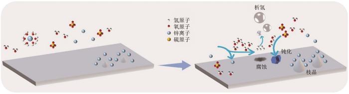
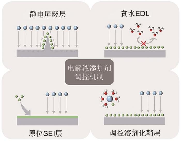
Aqueous zinc metal batteries (AZMBs) are gaining popularity in large-scale energy storage owing to their low cost and high safety. However, the unstable nature of the zinc metal in conventional aqueous electrolytes leads to the occurrence of zinc dendrite and side reactions such as hydrogen evolution and corrosion tend to occur at the interface, ultimately resulting in a shorter cycling life of AZMBs. To effectively regulate the chemical properties and reaction processes at the zinc anode interface and improve interfacial stability, electrolyte additive are used that can greatly extend the cycling life of AZMBs. Therefore, it is highly necessary to summarize the relevant research on electrolyte additives stabilizing the zinc anode, and propose new solutions to the key issues currently present. This paper provides examines the literature on the challenges faced and mechanisms of zinc anode, emphasizing the regulation mechanisms of electrolyte additives, including the design of an electrostatic shielding layer, water-poor double electric layer, in situ solid electrolyte interface layer and regulation of the zinc-ion solvation shell. In addition, different types of additives were classified and discussed, including cationic, anionic, organic small molecule, organic polymer, and others, and their respective regulation mechanisms and effects on electrochemical performance were analyzed. Ultimately, the study proposes new prospects for the development of electrolyte additive strategies to stabilize zinc negative electrodes.
SHI Wenchao. Research progress and prospect on electrolyte additives for stabilizing the zinc anode interface in aqueous batteries[J]. Energy Storage Science and Technology, 2023, 12(5): 1589-1603
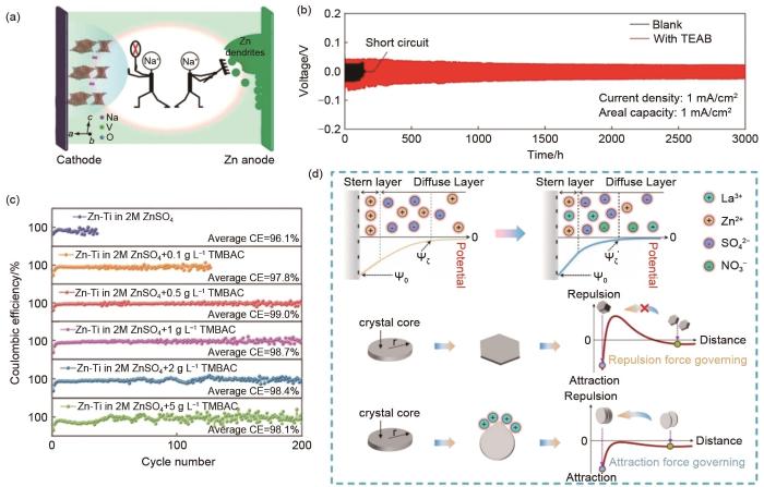
Fig. 3
(a) Schematic diagram of Na+ inhibiting the dissolution of NaV3O8·1.5H2O and zinc dendrite formation[46]; (b) The cycling performance of Zn-Zn symmetrical cells with or without TEAB[67]; (c) Coulomb efficiency performances of Zn-Ti cells in different concentrations of electrolyte additives[75]; (d) Schematic diagram of coherent deposition of zinc particles induced by a compressed double electric layer[77]
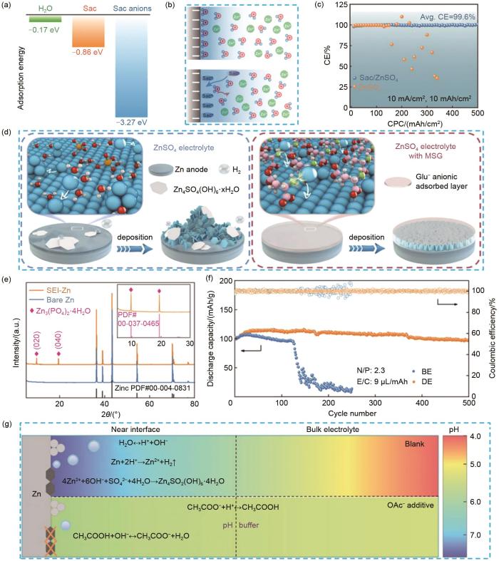
Fig. 4
(a) The adsorption energy of H2O, Sac, and Sac anions on Zn (0001) surface[69]; (b) The schematic descriptions of EDL structure before and after introducing Sac[69]; (c) The CE of Zn-Cu cells using Sac/ZnSO4 and ZnSO4 electrolyte[69]; (d) Schematic of Zn/electrolyte interface behaviors during Zn deposition in ZnSO4 and ZnSO4 electrolyte with MSG[78]; (e) XRD patterns of Zn electrode before and after 20 cycles in the designed electrolyte[71]; (f) Plot of long cycle performance and efficiency of Zn-V2O5 cells at 0.8 A/g current density[71]; (g) Schematic illustration of the pH evolution of different electrolytes and the interfacial pH buffer mechanism enabled by the OAc-anion[79]
Fig. 5
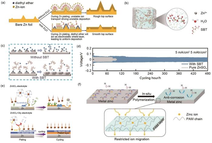
(a) Schematics of morphology evolution for Zn anodes in mild aqueous electrolyte with and without Et2O additive during Zn deposition/dissolution cycling[68]; (b) 3D snapshot of ZnSO4-SBT system and partial enlarged image representing Zn2+ solvation shell structure[81]; (c) Schematic diagram of Zn2+ deposition process in electrolyte system without SBT and with SBT[81]; (d) Long cycle performance of Zn-Zn symmetrical cells in ZnSO4 and ZnSO4-SBT[81]; (e) Schematics of deposition for Zn anodes in ZnSO4 and ZnSO4 with Gly additive systems[50]; (f) Schematic diagram of zinc deposition in AM additive[83]
Fig. 6
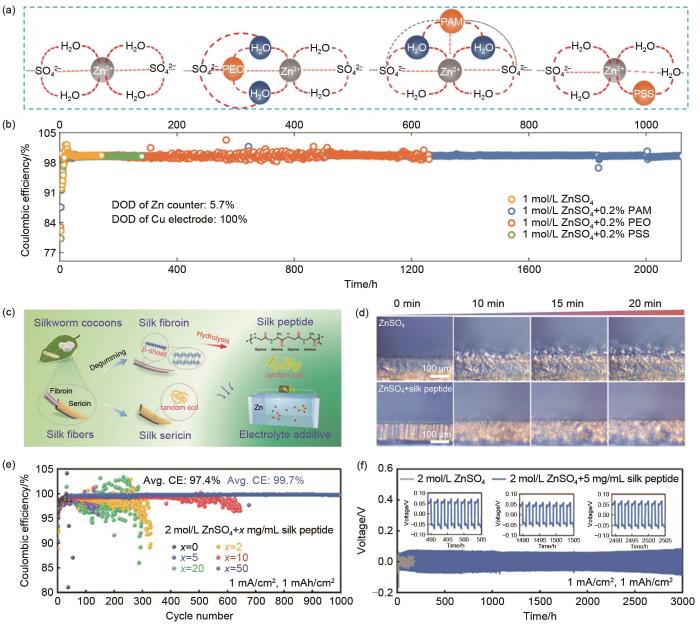
(a) Schematic diagrams of the bonding networks in different aqueous electrolytes with and without polymer additives[87]; (b) Coulombic efficiency and cycling performance of Zn anodes in 1 mol/L ZnSO4 aqueous electrolytes with different polymer additives using the Zn-Cu cells under 1 mA/cm2, 1 mAh/cm2[87]; (c) Schematic illustration of the relationship among silk sericin, fibroin, and peptide molecules with diverse conformations and polar groups, and their applications as electrolyte additives in AZMBs[89]; (d) In situ optical observations of Zn deposition morphologies in the ZnSO4 electrolytes with/without silk peptide at a current density of 10 mA/cm2[89]; (e) Coulomb efficiency of Zn-Cu cells in ZnSO4 electrolyte containing different concentrations of silk peptide additive[89]; (f) Cycling performance of Zn-Zn symmetric cells in the ZnSO4 aqueous electrolytes with/without silk peptide[89]
Fig. 7
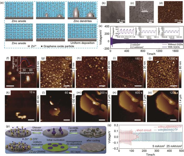
(a) The electric field distribution on the surface of zinc anode with and without GO electrolyte additive. The vectorial field describes the direction of the electric field[91]; (b)—(c) TEM and HRTEM (insert in c) images of as-prepared GQDs[92]; (d) AFM image of the GQDs on the mica substrate and corresponding height profile of the origin line A-B[92]; (e) Long-term cycling profiles of the Zn||Zn symmetric cells with and without GQDs additive at 2 mA/cm2 and the corresponding voltage profiles[92]; (f) Pristine C3N4QDs on mica (left) and the C3N4QDs in ZnSO4 aqueous electrolyte on HOPG (right), the inset is the height profiles of the corresponding lines[93]; (g)—(o) In situ AFM images of Zn electrodeposits on HOPG with a current density of 100 µA/cm2 in electrolyte with C3N4QDs (g)—(j) and without C3N4QDs (k)—(o)[93]; (p) Schematic illustration of using [BMIM]OTF additive to stabilize the Zn deposition process[95]; (q) Cycling performances at 5 mA/cm2 and 25 mAh/cm2[95]
CAO J, ZHANG D D, ZHANG X Y, et al. A universal and facile approach to suppress dendrite formation for a Zn and Li metal anode[J]. Journal of Materials Chemistry A, 2020, 8(18): 9331-9344.
CHOI J W, AURBACH D. Promise and reality of post-lithium-ion batteries with high energy densities[J]. Nature Reviews Materials, 2016, 1(4): 1-16.
LI M, LU J, CHEN Z W, et al. 30 years of lithium-ion batteries[J]. Advanced Materials (Deerfield Beach, Fla), 2018, 30(33): doi:10.1002/adma.201800561.
ZENG X H, HAO J N, WANG Z J, et al. Recent progress and perspectives on aqueous Zn-based rechargeable batteries with mild aqueous electrolytes[J]. Energy Storage Materials, 2019, 20: 410-437.
GUO X, ZHOU J, BAI C L, et al. Zn/MnO2 battery chemistry with dissolution-deposition mechanism[J]. Materials Today Energy, 2020, 16: doi: 10.1016/j.mtener.2020.100396.
CHAO D L, ZHU C R, SONG M, et al. A high-rate and stable quasi-solid-state zinc-ion battery with novel 2D layered zinc orthovanadate array[J]. Advanced Materials (Deerfield Beach, Fla), 2018, 30(32): doi: 10.1002/adma.201803181.
JIA X X, LIU C F, NEALE Z G, et al. Active materials for aqueous zinc ion batteries: Synthesis, crystal structure, morphology, and electrochemistry[J]. Chemical Reviews, 2020, 120(15): 7795-7866.
KUNDU D P, ADAMS B D, DUFFORT V, et al. A high-capacity and long-life aqueous rechargeable zinc battery using a metal oxide intercalation cathode[J]. Nature Energy, 2016, 1(10): 1-8.
KONAROV A, VORONINA N, JO J H, et al. Present and future perspective on electrode materials for rechargeable zinc-ion batteries[J]. ACS Energy Letters, 2018, 3(10): 2620-2640.
CHEN L N, AN Q Y, MAI L Q. Recent advances and prospects of cathode materials for rechargeable aqueous zinc-ion batteries[J]. Advanced Materials Interfaces, 2019, 6(17): doi: 10.1002/admi.201900387.
MA L, SCHROEDER M A, BORODIN O, et al. Realizing high zinc reversibility in rechargeable batteries[J]. Nature Energy, 2020, 5(10): 743-749.
DAI Y H, LIAO X B, YU R H, et al. Quicker and more Zn2+ storage predominantly from the interface[J]. Advanced Materials (Deerfield Beach, Fla), 2021, 33(26): doi: 10.1002/adma.202100359.
LI M, ZHANG Y X, HU J S, et al. Universal multifunctional hydrogen bond network construction strategy for enhanced aqueous Zn2+/proton hybrid batteries[J]. Nano Energy, 2022, 100: doi: 10.1016/j.nanoen.2022.107539.
WU B K, LUO W, LI M, et al. Achieving better aqueous rechargeable zinc ion batteries with heterostructure electrodes[J]. Nano Research, 2021, 14(9): 3174-3187.
MA L T, ZHI C Y. Zn electrode/electrolyte interfaces of Zn batteries: A mini review[J]. Electrochemistry Communications, 2021, 122: doi: 10.1016/j.elecom.2020.106898.
JIA H, WANG Z Q, TAWIAH B, et al. Recent advances in zinc anodes for high-performance aqueous Zn-ion batteries[J]. Nano Energy, 2020, 70: doi: 10.1016/j.nanoen.2020.104523.
HUANG J H, GUO Z W, MA Y Y, et al. Recent progress of rechargeable batteries using mild aqueous electrolytes[J]. Small Methods, 2019, 3(1): doi: 10.1002/smtd.201800272.
LI Y B, FU J, ZHONG C, et al. Recent advances in flexible zinc-based rechargeable batteries[J]. Advanced Energy Materials, 2019, 9(1): doi: 10.1002/aenm.201802605.
LI Y G, DAI H J. Recent advances in zinc-air batteries[J]. Chemical Society Reviews, 2014, 43(15): 5257-5275.
WANG Z, HUANG J H, GUO Z W, et al. A metal-organic framework host for highly reversible dendrite-free zinc metal anodes[J]. Joule, 2019, 3(5): 1289-1300.
XIE X S, LIANG S Q, GAO J W, et al. Manipulating the ion-transfer kinetics and interface stability for high-performance zinc metal anodes[J]. Energy & Environmental Science, 2020, 13(2): 503-510.
WANG W X, HUANG G, WANG Y Z, et al. Organic acid etching strategy for dendrite suppression in aqueous zinc-ion batteries[J]. Advanced Energy Materials, 2022, 12(6): doi: 10.1002/aenm.202102797.
ZHANG Q, DAI Y H, ZHAO K N, et al. Dynamic reconstruction of Ni-Zn alloy solid-electrolyte interface for highly stable Zn anode[J]. Nano Research, 2022: 1-8.
HAO J N, LI B, LI X L, et al. An In-depth study of Zn metal surface chemistry for advanced aqueous Zn-ion batteries[J]. Advanced Materials (Deerfield Beach, Fla), 2020, 32(34): doi: 10.1002/adma.202003021.
HAO J N, LI X L, ZHANG S L, et al. Designing dendrite-free zinc anodes for advanced aqueous zinc batteries[J]. Advanced Functional Materials, 2020, 30(30): doi: 10.1002/adfm.202001263.
PARK S H, BYEON S Y, PARK J H, et al. Insight into the critical role of surface hydrophilicity for dendrite-free zinc metal anodes[J]. ACS Energy Letters, 2021, 6(9): 3078-3085.
DENG C B, XIE X S, HAN J W, et al. Stabilization of Zn metal anode through surface reconstruction of a cerium-based conversion film[J]. Advanced Functional Materials, 2021, 31(51): doi: 10.1002/adfm.202103227.
KANG L T, CUI M W, JIANG F Y, et al. Nanoporous CaCO3 coatings enabled uniform Zn stripping/plating for long-life zinc rechargeable aqueous batteries[J]. Advanced Energy Materials, 2018, 8(25): doi: 10.1002/aenm.201801090.
YANG H J, CHANG Z, QIAO Y, et al. Constructing a super-saturated electrolyte front surface for stable rechargeable aqueous zinc batteries[J]. Angewandte Chemie (International Ed in English), 2020, 59(24): 9377-9381.
ZHOU X, CHEN R P, CUI E H, et al. A novel hydrophobic-zincophilic bifunctional layer for stable Zn metal anodes[J]. Energy Storage Materials, 2023, 55: 538-545.
LIU Y, GUO T, LIU Q, et al. Ultrathin ZrO2 coating layer regulates Zn deposition and raises long-life performance of aqueous Zn batteries[J]. Materials Today Energy, 2022, 28: doi: 10.1016/j.mtener.2022.101056.
WANG Z Q, DONG L B, HUANG W Y, et al. Simultaneously regulating uniform Zn2+ flux and electron conduction by MOF/rGO interlayers for high-performance Zn anodes[J]. Nano-Micro Letters, 2021, 13(1): doi: 10.1007/s40820-021-00594-7.
LI C, SUN Z T, YANG T, et al. Directly grown vertical graphene carpets as Janus separators toward stabilized Zn metal anodes[J]. Advanced Materials, 2020, 32(33): doi: 10.1002/adma.202003425.
QIN Y, LIU P, ZHANG Q, et al. Advanced filter membrane separator for aqueous zinc-ion batteries[J]. Small, 2020, 16(39): doi: 10.1002/smll.202003106.
MA L T, CHEN S M, LI X L, et al. Liquid-free all-solid-state zinc batteries and encapsulation-free flexible batteries enabled by in situ constructed polymer electrolyte[J]. Angewandte Chemie, 2020, 59(52): 23836-23844.
WAN F, ZHANG L L, DAI X, et al. Aqueous rechargeable zinc/sodium vanadate batteries with enhanced performance from simultaneous insertion of dual carriers[J]. Nature Communications, 2018, 9(1): 1-11.
GENG L S, MENG J S, WANG X P, et al. Eutectic electrolyte with unique solvation structure for high-performance zinc-ion batteries[J]. Angewandte Chemie, 2022, 61(31): doi: 10.1002/anie.202206717.
GENG L S, WANG X P, HAN K, et al. Eutectic electrolytes in advanced metal-ion batteries[J]. ACS Energy Letters, 2022, 7(1): 247-260.
LI M, WANG X P, HU J S, et al. Comprehensive H2O molecules regulation via deep eutectic solvents for ultra-stable zinc metal anode[J]. Angewandte Chemie International Edition, 2023, 62(8): doi: 10.1002/anie.202215552.
LIU Y, AN Y K, WU L, et al. Interfacial chemistry modulation via amphoteric glycine for a highly reversible zinc anode[J]. ACS Nano, 2023, 17(1): 552-560.
LIU Q, CHEN R P, XU L, et al. Steric molecular combing effect enables ultrafast self-healing electrolyte in quasi-solid-state zinc-ion batteries[J]. ACS Energy Letters, 2022, 7(8): 2825-2832.
XING Z H, HUANG C D, HU Z L. Advances and strategies in electrolyte regulation for aqueous zinc-based batteries[J]. Coordination Chemistry Reviews, 2022, 452: doi: 10.1016/j.ccr.2021.214299.
YAN H H, ZHANG X K, YANG Z W, et al. Insight into the electrolyte strategies for aqueous zinc ion batteries[J]. Coordination Chemistry Reviews, 2022, 452: doi: 10.1016/j.ccr.2021.214297.
DU Y X, LI Y, XU B B, et al. Electrolyte salts and additives regulation enables high performance aqueous zinc ion batteries: A mini review[J]. Small (Weinheim an Der Bergstrasse, Germany), 2022, 18(43): doi: 10.1002/smll.202104640.
GUO S, QIN L P, ZHANG T S, et al. Fundamentals and perspectives of electrolyte additives for aqueous zinc-ion batteries[J]. Energy Storage Materials, 2021, 34: 545-562.
GAO P, RU Q, YAN H L, et al. A durable Na0.56V2O5 nanobelt cathode material assisted by hybrid cationic electrolyte for high-performance aqueous zinc-ion batteries[J]. ChemElectroChem, 2020, 7(1): 283-288.
LASKA C A, AUINGER M, BIEDERMANN P U, et al. Effect of hydrogen carbonate and chloride on zinc corrosion investigated by a scanning flow cell system[J]. Electrochimica Acta, 2015, 159: 198-209.
TANG B Y, SHAN L T, LIANG S Q, et al. Issues and opportunities facing aqueous zinc-ion batteries[J]. Energy & Environmental Science, 2019, 12(11): 3288-3304.
YUAN L B, HAO J N, KAO C C, et al. Regulation methods for the Zn/electrolyte interphase and the effectiveness evaluation in aqueous Zn-ion batteries[J]. Energy & Environmental Science, 2021, 14(11): 5669-5689.
WANG F, HU E Y, SUN W, et al. A rechargeable aqueous Zn2+-battery with high power density and a long cycle-life[J]. Energy & Environmental Science, 2018, 11(11): 3168-3175.
DING F, XU W, GRAFF G L, et al. Dendrite-free lithium deposition via self-healing electrostatic shield mechanism[J]. Journal of the American Chemical Society, 2013, 135(11): 4450-4456.
WANG P J, XIE X S, XING Z Y, et al. Mechanistic insights of Mg2+-electrolyte additive for high-energy and long-life zinc-ion hybrid capacitors[J]. Advanced Energy Materials, 2021, 11(30): doi: 10.1002/aenm.202101158.
QIU Q L, CHI X W, HUANG J Q, et al. Highly stable plating/stripping behavior of zinc metal anodes in aqueous zinc batteries regulated by quaternary ammonium cationic salts[J]. ChemElectroChem, 2021, 8(5): 858-865.
XU W N, ZHAO K N, HUO W C, et al. Diethyl ether as self-healing electrolyte additive enabled long-life rechargeable aqueous zinc ion batteries[J]. Nano Energy, 2019, 62: 275-281.
ZHAO Z M, ZHAO J W, HU Z L, et al. Long-life and deeply rechargeable aqueous Zn anodes enabled by a multifunctional brightener-inspired interphase[J]. Energy & Environmental Science, 2019, 12(6): 1938-1949.
ZENG X H, MAO J F, HAO J N, et al. Electrolyte design for in situ construction of highly Zn2+-conductive solid electrolyte interphase to enable high-performance aqueous Zn-ion batteries under practical conditions[J]. Advanced Materials (Deerfield Beach, Fla), 2021, 33(11): doi: 10.1002/adma.202007416.
HAO J N, YUAN L B, YE C, et al. Boosting zinc electrode reversibility in aqueous electrolytes by using low-cost antisolvents[J]. Angewandte Chemie, 2021, 60(13): 7366-7375.
CHANG Z, YANG H, QIAO Y, et al. Tailoring the solvation sheath of cations by constructing electrode front‐faces for rechargeable batteries[J]. Advanced Materials, 2022: doi: 10.1002/adma.202201339.
BAYAGUUD A, LUO X, FU Y P, et al. Cationic surfactant-type electrolyte additive enables three-dimensional dendrite-free zinc anode for stable zinc-ion batteries[J]. ACS Energy Letters, 2020, 5(9): 3012-3020.
GUAN K L, TAO L, YANG R, et al. Anti-corrosion for reversible zinc anode via a hydrophobic interface in aqueous zinc batteries[J]. Advanced Energy Materials, 2022, 12(9): doi: 10.1002/aenm.202103557.
LI Y H, WU P F, ZHONG W, et al. A progressive nucleation mechanism enables stable zinc stripping-plating behavior[J]. Energy & Environmental Science, 2021, 14(10): 5563-5571.
ZHAO R R, WANG H F, DU H R, et al. Lanthanum nitrate as aqueous electrolyte additive for favourable zinc metal electrodeposition[J]. Nature Communications, 2022, 13(1): 1-9.
ZHONG Y, CHENG Z X, ZHANG H W, et al. Monosodium glutamate, an effective electrolyte additive to enhance cycling performance of Zn anode in aqueous battery[J]. Nano Energy, 2022, 98: doi: 10.1016/j.nanoen.2022.107220.
HAN D L, WANG Z X, LU H T, et al. A self-regulated interface toward highly reversible aqueous zinc batteries[J]. Advanced Energy Materials, 2022, 12(9): doi: 10.1002/aenm.202102982.
ZHANG W, DAI Y H, CHEN R W, et al. Highly reversible zinc metal anode in a dilute aqueous electrolyte enabled by a pH buffer additive[J]. Angewandte Chemie, 2023, 62(5): doi: 10.1002/anie.202212695.
QIU M J, SUN P, QIN A M, et al. Metal-coordination chemistry guiding preferred crystallographic orientation for reversible zinc anode[J]. Energy Storage Materials, 2022, 49: 463-470.
WU Z Z, LI M, TIAN Y H, et al. Cyclohexanedodecol-assisted interfacial engineering for robust and high-performance zinc metal anode[J]. Nano-Micro Letters, 2022, 14(1): doi: 10.1007/s40820-022-00846-0.
ZHANG D H, WARREN A J, LI G J, et al. Electrodeposition of zinc in aqueous electrolytes containing high molecular weight polymers[J]. Macromolecules, 2020, 53(7): 2694-2701.
YAN M D, XU C L, SUN Y, et al. Manipulating Zn anode reactions through salt anion involving hydrogen bonding network in aqueous electrolytes with PEO additive[J]. Nano Energy, 2021, 82: doi: 10.1016/j.nanoen.2020.105739.
JIN Y, HAN K S, SHAO Y Y, et al. Stabilizing zinc anode reactions by polyethylene oxide polymer in mild aqueous electrolytes[J]. Advanced Functional Materials, 2020, 30(43): doi: 10.1002/adfm.202003932.
YAN M D, DONG N L, ZHAO X S, et al. Tailoring the stability and kinetics of Zn anodes through trace organic polymer additives in dilute aqueous electrolyte[J]. ACS Energy Letters, 2021, 6(9): 3236-3243.
GUO G L, TAN X P, WANG K D, et al. High-efficiency and stable Zn-Na3V2(PO4)3 aqueous battery enabled by electrolyte-induced interphasial engineering[J]. ChemSusChem, 2022, 15(11): doi: 10.1002/cssc.202200313.
ABDULLA J, CAO J, ZHANG D D, et al. Elimination of zinc dendrites by graphene oxide electrolyte additive for zinc-ion batteries[J]. ACS Applied Energy Materials, 2021, 4(5): 4602-4609.
ZHANG W Y, DONG M Y, JIANG K R, et al. Self-repairing interphase reconstructed in each cycle for highly reversible aqueous zinc batteries[J]. Nature Communications, 2022, 13(1): 1-12.
PERIYAPPERUMA K, POZO-GONZALO C, MACFARLANE D R, et al. High Zn concentration pyrrolidinium-dicyanamide-based ionic liquid electrolytes for Zn2+/Zn0 electrochemistry in a flow environment[J]. ACS Applied Energy Materials, 2018, 1(9): 4580-4590.
CHEN J Z, ZHOU W J, QUAN Y H, et al. Ionic liquid additive enabling anti-freezing aqueous electrolyte and dendrite-free Zn metal electrode with organic/inorganic hybrid solid electrolyte interphase layer[J]. Energy Storage Materials, 2022, 53: 629-637.
... [46];(b) 在有或没有TEAB的Zn-Zn对称电池的循环性能[67];(c) 在不同浓度电解液添加剂中Zn-Ti电池的库仑效率性能[75];(d) 由压缩双电层诱发的锌粒子相干沉积示意图[77](a) Schematic diagram of Na<sup>+</sup> inhibiting the dissolution of NaV<sub>3</sub>O<sub>8</sub>·1.5H<sub>2</sub>O and zinc dendrite formation<sup>[<xref ref-type="bibr" rid="R46">46</xref>]</sup>; (b) The cycling performance of Zn-Zn symmetrical cells with or without TEAB<sup>[<xref ref-type="bibr" rid="R67">67</xref>]</sup>; (c) Coulomb efficiency performances of Zn-Ti cells in different concentrations of electrolyte additives<sup>[<xref ref-type="bibr" rid="R75">75</xref>]</sup>; (d) Schematic diagram of coherent deposition of zinc particles induced by a compressed double electric layer<sup>[<xref ref-type="bibr" rid="R77">77</xref>]</sup>Fig. 33.1.2 阴离子型添加剂
... [46]; (b) The cycling performance of Zn-Zn symmetrical cells with or without TEAB[67]; (c) Coulomb efficiency performances of Zn-Ti cells in different concentrations of electrolyte additives[75]; (d) Schematic diagram of coherent deposition of zinc particles induced by a compressed double electric layer[77]Fig. 33.1.2 阴离子型添加剂
... [50];(f) 在含AM添加剂中锌沉积示意图[83](a) Schematics of morphology evolution for Zn anodes in mild aqueous electrolyte with and without Et<sub>2</sub>O additive during Zn deposition/dissolution cycling<sup>[<xref ref-type="bibr" rid="R68">68</xref>]</sup>; (b) 3D snapshot of ZnSO<sub>4</sub>-SBT system and partial enlarged image representing Zn<sup>2+</sup> solvation shell structure<sup>[<xref ref-type="bibr" rid="R81">81</xref>]</sup>; (c) Schematic diagram of Zn<sup>2+</sup> deposition process in electrolyte system without SBT and with SBT<sup>[<xref ref-type="bibr" rid="R81">81</xref>]</sup>; (d) Long cycle performance of Zn-Zn symmetrical cells in ZnSO<sub>4</sub> and ZnSO<sub>4</sub>-SBT<sup>[<xref ref-type="bibr" rid="R81">81</xref>]</sup>; (e) Schematics of deposition for Zn anodes in ZnSO<sub>4</sub> and ZnSO<sub>4</sub> with Gly additive systems<sup>[<xref ref-type="bibr" rid="R50">50</xref>]</sup>; (f) Schematic diagram of zinc deposition in AM additive<sup>[<xref ref-type="bibr" rid="R83">83</xref>]</sup>Fig. 53.2.2 有机聚合物型添加剂
... [67];(c) 在不同浓度电解液添加剂中Zn-Ti电池的库仑效率性能[75];(d) 由压缩双电层诱发的锌粒子相干沉积示意图[77](a) Schematic diagram of Na<sup>+</sup> inhibiting the dissolution of NaV<sub>3</sub>O<sub>8</sub>·1.5H<sub>2</sub>O and zinc dendrite formation<sup>[<xref ref-type="bibr" rid="R46">46</xref>]</sup>; (b) The cycling performance of Zn-Zn symmetrical cells with or without TEAB<sup>[<xref ref-type="bibr" rid="R67">67</xref>]</sup>; (c) Coulomb efficiency performances of Zn-Ti cells in different concentrations of electrolyte additives<sup>[<xref ref-type="bibr" rid="R75">75</xref>]</sup>; (d) Schematic diagram of coherent deposition of zinc particles induced by a compressed double electric layer<sup>[<xref ref-type="bibr" rid="R77">77</xref>]</sup>Fig. 33.1.2 阴离子型添加剂
... [67]; (c) Coulomb efficiency performances of Zn-Ti cells in different concentrations of electrolyte additives[75]; (d) Schematic diagram of coherent deposition of zinc particles induced by a compressed double electric layer[77]Fig. 33.1.2 阴离子型添加剂
... [68];(b) ZnSO4-SBT体系的三维快照和部分放大图像代表Zn2+ 的溶剂化鞘层结构[81];(c) 在无SBT和有SBT的电解液体系下Zn2+ 的沉积过程示意图[81];(d) 在ZnSO4 和添加SBT的ZnSO4 电解液中,Zn-Zn对称电池的长循环性能[81];(e) 在ZnSO4 和添加Gly的ZnSO4 电解液中的锌负极沉积示意图[50];(f) 在含AM添加剂中锌沉积示意图[83](a) Schematics of morphology evolution for Zn anodes in mild aqueous electrolyte with and without Et<sub>2</sub>O additive during Zn deposition/dissolution cycling<sup>[<xref ref-type="bibr" rid="R68">68</xref>]</sup>; (b) 3D snapshot of ZnSO<sub>4</sub>-SBT system and partial enlarged image representing Zn<sup>2+</sup> solvation shell structure<sup>[<xref ref-type="bibr" rid="R81">81</xref>]</sup>; (c) Schematic diagram of Zn<sup>2+</sup> deposition process in electrolyte system without SBT and with SBT<sup>[<xref ref-type="bibr" rid="R81">81</xref>]</sup>; (d) Long cycle performance of Zn-Zn symmetrical cells in ZnSO<sub>4</sub> and ZnSO<sub>4</sub>-SBT<sup>[<xref ref-type="bibr" rid="R81">81</xref>]</sup>; (e) Schematics of deposition for Zn anodes in ZnSO<sub>4</sub> and ZnSO<sub>4</sub> with Gly additive systems<sup>[<xref ref-type="bibr" rid="R50">50</xref>]</sup>; (f) Schematic diagram of zinc deposition in AM additive<sup>[<xref ref-type="bibr" rid="R83">83</xref>]</sup>Fig. 53.2.2 有机聚合物型添加剂
... [68]; (b) 3D snapshot of ZnSO4-SBT system and partial enlarged image representing Zn2+ solvation shell structure[81]; (c) Schematic diagram of Zn2+ deposition process in electrolyte system without SBT and with SBT[81]; (d) Long cycle performance of Zn-Zn symmetrical cells in ZnSO4 and ZnSO4-SBT[81]; (e) Schematics of deposition for Zn anodes in ZnSO4 and ZnSO4 with Gly additive systems[50]; (f) Schematic diagram of zinc deposition in AM additive[83]Fig. 53.2.2 有机聚合物型添加剂
... [69];(b) 锌负极界面在引入Sac添加剂前后的EDL结构示意图[69];(c) 在Sac/ZnSO4 和ZnSO4 电解液中Zn-Cu电池的库仑效率[69];(d) 在ZnSO4 和添加MSG的ZnSO4 电解液中,锌/电解液界面沉积行为示意图[78];(e) 在设计的电解液中循环20次前后锌电极的XRD谱图[71];(f) Zn-V2O5 电池在0.8 A/g的电流密度下的长循环性能和效率图[71];(g) 不同电解液pH演变和OAc-阴离子诱导的界面pH缓冲机制的示意图[79]<strong>(a) The adsorption energy of H<sub>2</sub>O, Sac, and Sac anions on Zn (0001) surface</strong><sup>[<xref ref-type="bibr" rid="R69">69</xref>]</sup><strong>; (b) The schematic descriptions of EDL structure before and after introducing Sac</strong><sup>[<xref ref-type="bibr" rid="R69">69</xref>]</sup><strong>; (c) The CE of Zn-Cu cells using Sac/ZnSO<sub>4</sub> and ZnSO<sub>4</sub> electrolyte</strong><sup>[<xref ref-type="bibr" rid="R69">69</xref>]</sup><strong>; (d) Schematic of Zn/electrolyte interface behaviors during Zn deposition in ZnSO<sub>4</sub> and ZnSO<sub>4</sub> electrolyte with MSG</strong><sup>[<xref ref-type="bibr" rid="R78">78</xref>]</sup><strong>; (e) XRD patterns of Zn electrode before and after 20 cycles in the designed electrolyte</strong><sup>[<xref ref-type="bibr" rid="R71">71</xref>]</sup><strong>; (f) Plot of long cycle performance and efficiency of Zn-V<sub>2</sub>O<sub>5</sub> cells at 0.8 A/g current density</strong><sup>[<xref ref-type="bibr" rid="R71">71</xref>]</sup><strong>; (g) Schematic illustration of the pH evolution of different electrolytes and the interfacial pH buffer mechanism enabled by the OAc</strong><sup>-</sup><strong>anion</strong><sup>[<xref ref-type="bibr" rid="R79">79</xref>]</sup>Fig. 4<strong>3.2</strong> 有机添加剂
... [69];(c) 在Sac/ZnSO4 和ZnSO4 电解液中Zn-Cu电池的库仑效率[69];(d) 在ZnSO4 和添加MSG的ZnSO4 电解液中,锌/电解液界面沉积行为示意图[78];(e) 在设计的电解液中循环20次前后锌电极的XRD谱图[71];(f) Zn-V2O5 电池在0.8 A/g的电流密度下的长循环性能和效率图[71];(g) 不同电解液pH演变和OAc-阴离子诱导的界面pH缓冲机制的示意图[79]<strong>(a) The adsorption energy of H<sub>2</sub>O, Sac, and Sac anions on Zn (0001) surface</strong><sup>[<xref ref-type="bibr" rid="R69">69</xref>]</sup><strong>; (b) The schematic descriptions of EDL structure before and after introducing Sac</strong><sup>[<xref ref-type="bibr" rid="R69">69</xref>]</sup><strong>; (c) The CE of Zn-Cu cells using Sac/ZnSO<sub>4</sub> and ZnSO<sub>4</sub> electrolyte</strong><sup>[<xref ref-type="bibr" rid="R69">69</xref>]</sup><strong>; (d) Schematic of Zn/electrolyte interface behaviors during Zn deposition in ZnSO<sub>4</sub> and ZnSO<sub>4</sub> electrolyte with MSG</strong><sup>[<xref ref-type="bibr" rid="R78">78</xref>]</sup><strong>; (e) XRD patterns of Zn electrode before and after 20 cycles in the designed electrolyte</strong><sup>[<xref ref-type="bibr" rid="R71">71</xref>]</sup><strong>; (f) Plot of long cycle performance and efficiency of Zn-V<sub>2</sub>O<sub>5</sub> cells at 0.8 A/g current density</strong><sup>[<xref ref-type="bibr" rid="R71">71</xref>]</sup><strong>; (g) Schematic illustration of the pH evolution of different electrolytes and the interfacial pH buffer mechanism enabled by the OAc</strong><sup>-</sup><strong>anion</strong><sup>[<xref ref-type="bibr" rid="R79">79</xref>]</sup>Fig. 4<strong>3.2</strong> 有机添加剂
... [69];(d) 在ZnSO4 和添加MSG的ZnSO4 电解液中,锌/电解液界面沉积行为示意图[78];(e) 在设计的电解液中循环20次前后锌电极的XRD谱图[71];(f) Zn-V2O5 电池在0.8 A/g的电流密度下的长循环性能和效率图[71];(g) 不同电解液pH演变和OAc-阴离子诱导的界面pH缓冲机制的示意图[79]<strong>(a) The adsorption energy of H<sub>2</sub>O, Sac, and Sac anions on Zn (0001) surface</strong><sup>[<xref ref-type="bibr" rid="R69">69</xref>]</sup><strong>; (b) The schematic descriptions of EDL structure before and after introducing Sac</strong><sup>[<xref ref-type="bibr" rid="R69">69</xref>]</sup><strong>; (c) The CE of Zn-Cu cells using Sac/ZnSO<sub>4</sub> and ZnSO<sub>4</sub> electrolyte</strong><sup>[<xref ref-type="bibr" rid="R69">69</xref>]</sup><strong>; (d) Schematic of Zn/electrolyte interface behaviors during Zn deposition in ZnSO<sub>4</sub> and ZnSO<sub>4</sub> electrolyte with MSG</strong><sup>[<xref ref-type="bibr" rid="R78">78</xref>]</sup><strong>; (e) XRD patterns of Zn electrode before and after 20 cycles in the designed electrolyte</strong><sup>[<xref ref-type="bibr" rid="R71">71</xref>]</sup><strong>; (f) Plot of long cycle performance and efficiency of Zn-V<sub>2</sub>O<sub>5</sub> cells at 0.8 A/g current density</strong><sup>[<xref ref-type="bibr" rid="R71">71</xref>]</sup><strong>; (g) Schematic illustration of the pH evolution of different electrolytes and the interfacial pH buffer mechanism enabled by the OAc</strong><sup>-</sup><strong>anion</strong><sup>[<xref ref-type="bibr" rid="R79">79</xref>]</sup>Fig. 4<strong>3.2</strong> 有机添加剂
... [69]; (b) The schematic descriptions of EDL structure before and after introducing Sac[69]; (c) The CE of Zn-Cu cells using Sac/ZnSO4 and ZnSO4 electrolyte[69]; (d) Schematic of Zn/electrolyte interface behaviors during Zn deposition in ZnSO4 and ZnSO4 electrolyte with MSG[78]; (e) XRD patterns of Zn electrode before and after 20 cycles in the designed electrolyte[71]; (f) Plot of long cycle performance and efficiency of Zn-V2O5 cells at 0.8 A/g current density[71]; (g) Schematic illustration of the pH evolution of different electrolytes and the interfacial pH buffer mechanism enabled by the OAc-anion[79]Fig. 4<strong>3.2</strong> 有机添加剂
... [69]; (c) The CE of Zn-Cu cells using Sac/ZnSO4 and ZnSO4 electrolyte[69]; (d) Schematic of Zn/electrolyte interface behaviors during Zn deposition in ZnSO4 and ZnSO4 electrolyte with MSG[78]; (e) XRD patterns of Zn electrode before and after 20 cycles in the designed electrolyte[71]; (f) Plot of long cycle performance and efficiency of Zn-V2O5 cells at 0.8 A/g current density[71]; (g) Schematic illustration of the pH evolution of different electrolytes and the interfacial pH buffer mechanism enabled by the OAc-anion[79]Fig. 4<strong>3.2</strong> 有机添加剂
... [69]; (d) Schematic of Zn/electrolyte interface behaviors during Zn deposition in ZnSO4 and ZnSO4 electrolyte with MSG[78]; (e) XRD patterns of Zn electrode before and after 20 cycles in the designed electrolyte[71]; (f) Plot of long cycle performance and efficiency of Zn-V2O5 cells at 0.8 A/g current density[71]; (g) Schematic illustration of the pH evolution of different electrolytes and the interfacial pH buffer mechanism enabled by the OAc-anion[79]Fig. 4<strong>3.2</strong> 有机添加剂
... [71];(f) Zn-V2O5 电池在0.8 A/g的电流密度下的长循环性能和效率图[71];(g) 不同电解液pH演变和OAc-阴离子诱导的界面pH缓冲机制的示意图[79]<strong>(a) The adsorption energy of H<sub>2</sub>O, Sac, and Sac anions on Zn (0001) surface</strong><sup>[<xref ref-type="bibr" rid="R69">69</xref>]</sup><strong>; (b) The schematic descriptions of EDL structure before and after introducing Sac</strong><sup>[<xref ref-type="bibr" rid="R69">69</xref>]</sup><strong>; (c) The CE of Zn-Cu cells using Sac/ZnSO<sub>4</sub> and ZnSO<sub>4</sub> electrolyte</strong><sup>[<xref ref-type="bibr" rid="R69">69</xref>]</sup><strong>; (d) Schematic of Zn/electrolyte interface behaviors during Zn deposition in ZnSO<sub>4</sub> and ZnSO<sub>4</sub> electrolyte with MSG</strong><sup>[<xref ref-type="bibr" rid="R78">78</xref>]</sup><strong>; (e) XRD patterns of Zn electrode before and after 20 cycles in the designed electrolyte</strong><sup>[<xref ref-type="bibr" rid="R71">71</xref>]</sup><strong>; (f) Plot of long cycle performance and efficiency of Zn-V<sub>2</sub>O<sub>5</sub> cells at 0.8 A/g current density</strong><sup>[<xref ref-type="bibr" rid="R71">71</xref>]</sup><strong>; (g) Schematic illustration of the pH evolution of different electrolytes and the interfacial pH buffer mechanism enabled by the OAc</strong><sup>-</sup><strong>anion</strong><sup>[<xref ref-type="bibr" rid="R79">79</xref>]</sup>Fig. 4<strong>3.2</strong> 有机添加剂
... [71];(g) 不同电解液pH演变和OAc-阴离子诱导的界面pH缓冲机制的示意图[79]<strong>(a) The adsorption energy of H<sub>2</sub>O, Sac, and Sac anions on Zn (0001) surface</strong><sup>[<xref ref-type="bibr" rid="R69">69</xref>]</sup><strong>; (b) The schematic descriptions of EDL structure before and after introducing Sac</strong><sup>[<xref ref-type="bibr" rid="R69">69</xref>]</sup><strong>; (c) The CE of Zn-Cu cells using Sac/ZnSO<sub>4</sub> and ZnSO<sub>4</sub> electrolyte</strong><sup>[<xref ref-type="bibr" rid="R69">69</xref>]</sup><strong>; (d) Schematic of Zn/electrolyte interface behaviors during Zn deposition in ZnSO<sub>4</sub> and ZnSO<sub>4</sub> electrolyte with MSG</strong><sup>[<xref ref-type="bibr" rid="R78">78</xref>]</sup><strong>; (e) XRD patterns of Zn electrode before and after 20 cycles in the designed electrolyte</strong><sup>[<xref ref-type="bibr" rid="R71">71</xref>]</sup><strong>; (f) Plot of long cycle performance and efficiency of Zn-V<sub>2</sub>O<sub>5</sub> cells at 0.8 A/g current density</strong><sup>[<xref ref-type="bibr" rid="R71">71</xref>]</sup><strong>; (g) Schematic illustration of the pH evolution of different electrolytes and the interfacial pH buffer mechanism enabled by the OAc</strong><sup>-</sup><strong>anion</strong><sup>[<xref ref-type="bibr" rid="R79">79</xref>]</sup>Fig. 4<strong>3.2</strong> 有机添加剂
... [71]; (f) Plot of long cycle performance and efficiency of Zn-V2O5 cells at 0.8 A/g current density[71]; (g) Schematic illustration of the pH evolution of different electrolytes and the interfacial pH buffer mechanism enabled by the OAc-anion[79]Fig. 4<strong>3.2</strong> 有机添加剂
... [71]; (g) Schematic illustration of the pH evolution of different electrolytes and the interfacial pH buffer mechanism enabled by the OAc-anion[79]Fig. 4<strong>3.2</strong> 有机添加剂
... [75];(d) 由压缩双电层诱发的锌粒子相干沉积示意图[77](a) Schematic diagram of Na<sup>+</sup> inhibiting the dissolution of NaV<sub>3</sub>O<sub>8</sub>·1.5H<sub>2</sub>O and zinc dendrite formation<sup>[<xref ref-type="bibr" rid="R46">46</xref>]</sup>; (b) The cycling performance of Zn-Zn symmetrical cells with or without TEAB<sup>[<xref ref-type="bibr" rid="R67">67</xref>]</sup>; (c) Coulomb efficiency performances of Zn-Ti cells in different concentrations of electrolyte additives<sup>[<xref ref-type="bibr" rid="R75">75</xref>]</sup>; (d) Schematic diagram of coherent deposition of zinc particles induced by a compressed double electric layer<sup>[<xref ref-type="bibr" rid="R77">77</xref>]</sup>Fig. 33.1.2 阴离子型添加剂
... [77](a) Schematic diagram of Na<sup>+</sup> inhibiting the dissolution of NaV<sub>3</sub>O<sub>8</sub>·1.5H<sub>2</sub>O and zinc dendrite formation<sup>[<xref ref-type="bibr" rid="R46">46</xref>]</sup>; (b) The cycling performance of Zn-Zn symmetrical cells with or without TEAB<sup>[<xref ref-type="bibr" rid="R67">67</xref>]</sup>; (c) Coulomb efficiency performances of Zn-Ti cells in different concentrations of electrolyte additives<sup>[<xref ref-type="bibr" rid="R75">75</xref>]</sup>; (d) Schematic diagram of coherent deposition of zinc particles induced by a compressed double electric layer<sup>[<xref ref-type="bibr" rid="R77">77</xref>]</sup>Fig. 33.1.2 阴离子型添加剂
... [78];(e) 在设计的电解液中循环20次前后锌电极的XRD谱图[71];(f) Zn-V2O5 电池在0.8 A/g的电流密度下的长循环性能和效率图[71];(g) 不同电解液pH演变和OAc-阴离子诱导的界面pH缓冲机制的示意图[79]<strong>(a) The adsorption energy of H<sub>2</sub>O, Sac, and Sac anions on Zn (0001) surface</strong><sup>[<xref ref-type="bibr" rid="R69">69</xref>]</sup><strong>; (b) The schematic descriptions of EDL structure before and after introducing Sac</strong><sup>[<xref ref-type="bibr" rid="R69">69</xref>]</sup><strong>; (c) The CE of Zn-Cu cells using Sac/ZnSO<sub>4</sub> and ZnSO<sub>4</sub> electrolyte</strong><sup>[<xref ref-type="bibr" rid="R69">69</xref>]</sup><strong>; (d) Schematic of Zn/electrolyte interface behaviors during Zn deposition in ZnSO<sub>4</sub> and ZnSO<sub>4</sub> electrolyte with MSG</strong><sup>[<xref ref-type="bibr" rid="R78">78</xref>]</sup><strong>; (e) XRD patterns of Zn electrode before and after 20 cycles in the designed electrolyte</strong><sup>[<xref ref-type="bibr" rid="R71">71</xref>]</sup><strong>; (f) Plot of long cycle performance and efficiency of Zn-V<sub>2</sub>O<sub>5</sub> cells at 0.8 A/g current density</strong><sup>[<xref ref-type="bibr" rid="R71">71</xref>]</sup><strong>; (g) Schematic illustration of the pH evolution of different electrolytes and the interfacial pH buffer mechanism enabled by the OAc</strong><sup>-</sup><strong>anion</strong><sup>[<xref ref-type="bibr" rid="R79">79</xref>]</sup>Fig. 4<strong>3.2</strong> 有机添加剂
... [78]; (e) XRD patterns of Zn electrode before and after 20 cycles in the designed electrolyte[71]; (f) Plot of long cycle performance and efficiency of Zn-V2O5 cells at 0.8 A/g current density[71]; (g) Schematic illustration of the pH evolution of different electrolytes and the interfacial pH buffer mechanism enabled by the OAc-anion[79]Fig. 4<strong>3.2</strong> 有机添加剂
... [79]<strong>(a) The adsorption energy of H<sub>2</sub>O, Sac, and Sac anions on Zn (0001) surface</strong><sup>[<xref ref-type="bibr" rid="R69">69</xref>]</sup><strong>; (b) The schematic descriptions of EDL structure before and after introducing Sac</strong><sup>[<xref ref-type="bibr" rid="R69">69</xref>]</sup><strong>; (c) The CE of Zn-Cu cells using Sac/ZnSO<sub>4</sub> and ZnSO<sub>4</sub> electrolyte</strong><sup>[<xref ref-type="bibr" rid="R69">69</xref>]</sup><strong>; (d) Schematic of Zn/electrolyte interface behaviors during Zn deposition in ZnSO<sub>4</sub> and ZnSO<sub>4</sub> electrolyte with MSG</strong><sup>[<xref ref-type="bibr" rid="R78">78</xref>]</sup><strong>; (e) XRD patterns of Zn electrode before and after 20 cycles in the designed electrolyte</strong><sup>[<xref ref-type="bibr" rid="R71">71</xref>]</sup><strong>; (f) Plot of long cycle performance and efficiency of Zn-V<sub>2</sub>O<sub>5</sub> cells at 0.8 A/g current density</strong><sup>[<xref ref-type="bibr" rid="R71">71</xref>]</sup><strong>; (g) Schematic illustration of the pH evolution of different electrolytes and the interfacial pH buffer mechanism enabled by the OAc</strong><sup>-</sup><strong>anion</strong><sup>[<xref ref-type="bibr" rid="R79">79</xref>]</sup>Fig. 4<strong>3.2</strong> 有机添加剂
... [81];(c) 在无SBT和有SBT的电解液体系下Zn2+ 的沉积过程示意图[81];(d) 在ZnSO4 和添加SBT的ZnSO4 电解液中,Zn-Zn对称电池的长循环性能[81];(e) 在ZnSO4 和添加Gly的ZnSO4 电解液中的锌负极沉积示意图[50];(f) 在含AM添加剂中锌沉积示意图[83](a) Schematics of morphology evolution for Zn anodes in mild aqueous electrolyte with and without Et<sub>2</sub>O additive during Zn deposition/dissolution cycling<sup>[<xref ref-type="bibr" rid="R68">68</xref>]</sup>; (b) 3D snapshot of ZnSO<sub>4</sub>-SBT system and partial enlarged image representing Zn<sup>2+</sup> solvation shell structure<sup>[<xref ref-type="bibr" rid="R81">81</xref>]</sup>; (c) Schematic diagram of Zn<sup>2+</sup> deposition process in electrolyte system without SBT and with SBT<sup>[<xref ref-type="bibr" rid="R81">81</xref>]</sup>; (d) Long cycle performance of Zn-Zn symmetrical cells in ZnSO<sub>4</sub> and ZnSO<sub>4</sub>-SBT<sup>[<xref ref-type="bibr" rid="R81">81</xref>]</sup>; (e) Schematics of deposition for Zn anodes in ZnSO<sub>4</sub> and ZnSO<sub>4</sub> with Gly additive systems<sup>[<xref ref-type="bibr" rid="R50">50</xref>]</sup>; (f) Schematic diagram of zinc deposition in AM additive<sup>[<xref ref-type="bibr" rid="R83">83</xref>]</sup>Fig. 53.2.2 有机聚合物型添加剂
... [81];(d) 在ZnSO4 和添加SBT的ZnSO4 电解液中,Zn-Zn对称电池的长循环性能[81];(e) 在ZnSO4 和添加Gly的ZnSO4 电解液中的锌负极沉积示意图[50];(f) 在含AM添加剂中锌沉积示意图[83](a) Schematics of morphology evolution for Zn anodes in mild aqueous electrolyte with and without Et<sub>2</sub>O additive during Zn deposition/dissolution cycling<sup>[<xref ref-type="bibr" rid="R68">68</xref>]</sup>; (b) 3D snapshot of ZnSO<sub>4</sub>-SBT system and partial enlarged image representing Zn<sup>2+</sup> solvation shell structure<sup>[<xref ref-type="bibr" rid="R81">81</xref>]</sup>; (c) Schematic diagram of Zn<sup>2+</sup> deposition process in electrolyte system without SBT and with SBT<sup>[<xref ref-type="bibr" rid="R81">81</xref>]</sup>; (d) Long cycle performance of Zn-Zn symmetrical cells in ZnSO<sub>4</sub> and ZnSO<sub>4</sub>-SBT<sup>[<xref ref-type="bibr" rid="R81">81</xref>]</sup>; (e) Schematics of deposition for Zn anodes in ZnSO<sub>4</sub> and ZnSO<sub>4</sub> with Gly additive systems<sup>[<xref ref-type="bibr" rid="R50">50</xref>]</sup>; (f) Schematic diagram of zinc deposition in AM additive<sup>[<xref ref-type="bibr" rid="R83">83</xref>]</sup>Fig. 53.2.2 有机聚合物型添加剂
... [81];(e) 在ZnSO4 和添加Gly的ZnSO4 电解液中的锌负极沉积示意图[50];(f) 在含AM添加剂中锌沉积示意图[83](a) Schematics of morphology evolution for Zn anodes in mild aqueous electrolyte with and without Et<sub>2</sub>O additive during Zn deposition/dissolution cycling<sup>[<xref ref-type="bibr" rid="R68">68</xref>]</sup>; (b) 3D snapshot of ZnSO<sub>4</sub>-SBT system and partial enlarged image representing Zn<sup>2+</sup> solvation shell structure<sup>[<xref ref-type="bibr" rid="R81">81</xref>]</sup>; (c) Schematic diagram of Zn<sup>2+</sup> deposition process in electrolyte system without SBT and with SBT<sup>[<xref ref-type="bibr" rid="R81">81</xref>]</sup>; (d) Long cycle performance of Zn-Zn symmetrical cells in ZnSO<sub>4</sub> and ZnSO<sub>4</sub>-SBT<sup>[<xref ref-type="bibr" rid="R81">81</xref>]</sup>; (e) Schematics of deposition for Zn anodes in ZnSO<sub>4</sub> and ZnSO<sub>4</sub> with Gly additive systems<sup>[<xref ref-type="bibr" rid="R50">50</xref>]</sup>; (f) Schematic diagram of zinc deposition in AM additive<sup>[<xref ref-type="bibr" rid="R83">83</xref>]</sup>Fig. 53.2.2 有机聚合物型添加剂
... [81]; (c) Schematic diagram of Zn2+ deposition process in electrolyte system without SBT and with SBT[81]; (d) Long cycle performance of Zn-Zn symmetrical cells in ZnSO4 and ZnSO4-SBT[81]; (e) Schematics of deposition for Zn anodes in ZnSO4 and ZnSO4 with Gly additive systems[50]; (f) Schematic diagram of zinc deposition in AM additive[83]Fig. 53.2.2 有机聚合物型添加剂
... [81]; (d) Long cycle performance of Zn-Zn symmetrical cells in ZnSO4 and ZnSO4-SBT[81]; (e) Schematics of deposition for Zn anodes in ZnSO4 and ZnSO4 with Gly additive systems[50]; (f) Schematic diagram of zinc deposition in AM additive[83]Fig. 53.2.2 有机聚合物型添加剂
... [81]; (e) Schematics of deposition for Zn anodes in ZnSO4 and ZnSO4 with Gly additive systems[50]; (f) Schematic diagram of zinc deposition in AM additive[83]Fig. 53.2.2 有机聚合物型添加剂
... [83](a) Schematics of morphology evolution for Zn anodes in mild aqueous electrolyte with and without Et<sub>2</sub>O additive during Zn deposition/dissolution cycling<sup>[<xref ref-type="bibr" rid="R68">68</xref>]</sup>; (b) 3D snapshot of ZnSO<sub>4</sub>-SBT system and partial enlarged image representing Zn<sup>2+</sup> solvation shell structure<sup>[<xref ref-type="bibr" rid="R81">81</xref>]</sup>; (c) Schematic diagram of Zn<sup>2+</sup> deposition process in electrolyte system without SBT and with SBT<sup>[<xref ref-type="bibr" rid="R81">81</xref>]</sup>; (d) Long cycle performance of Zn-Zn symmetrical cells in ZnSO<sub>4</sub> and ZnSO<sub>4</sub>-SBT<sup>[<xref ref-type="bibr" rid="R81">81</xref>]</sup>; (e) Schematics of deposition for Zn anodes in ZnSO<sub>4</sub> and ZnSO<sub>4</sub> with Gly additive systems<sup>[<xref ref-type="bibr" rid="R50">50</xref>]</sup>; (f) Schematic diagram of zinc deposition in AM additive<sup>[<xref ref-type="bibr" rid="R83">83</xref>]</sup>Fig. 53.2.2 有机聚合物型添加剂
... [87];(b) 在不同聚合物添加剂的1 mol/L ZnSO4 水溶液中,在1 mA/cm2 、1 mAh/cm2 的测试条件下,Zn-Cu电池的库仑效率和循环性能[87];(c) 丝胶蛋白、丝素蛋白和具有不同构象和极性基团的肽分子之间的关系示意图,以及它们在AZMBs中作为电解液添加剂的应用[89];(d) 在电流密度为10 mA/cm2 时,含/不含丝肽的ZnSO4 电解质中Zn沉积形貌的原位光学观察[89];(e) 在含不同浓度的丝肽添加剂的ZnSO4 电解液中Zn-Cu电池的库仑效率[89];(f) 在含/不含丝肽的ZnSO4 电解液中Zn-Zn对称电池的循环性能[89](a) Schematic diagrams of the bonding networks in different aqueous electrolytes with and without polymer additives<sup>[<xref ref-type="bibr" rid="R87">87</xref>]</sup>; (b) Coulombic efficiency and cycling performance of Zn anodes in 1 mol/L ZnSO<sub>4</sub> aqueous electrolytes with different polymer additives using the Zn-Cu cells under 1 mA/cm<sup>2</sup>, 1 mAh/cm<sup>2[<xref ref-type="bibr" rid="R87">87</xref>]</sup>; (c) Schematic illustration of the relationship among silk sericin, fibroin, and peptide molecules with diverse conformations and polar groups, and their applications as electrolyte additives in AZMBs<sup>[<xref ref-type="bibr" rid="R89">89</xref>]</sup>; (d) In situ optical observations of Zn deposition morphologies in the ZnSO<sub>4</sub> electrolytes with/without silk peptide at a current density of 10 mA/cm<sup>2[<xref ref-type="bibr" rid="R89">89</xref>]</sup>; (e) Coulomb efficiency of Zn-Cu cells in ZnSO<sub>4</sub> electrolyte containing different concentrations of silk peptide additive<sup>[<xref ref-type="bibr" rid="R89">89</xref>]</sup>; (f) Cycling performance of Zn-Zn symmetric cells in the ZnSO<sub>4</sub> aqueous electrolytes with/without silk peptide<sup>[<xref ref-type="bibr" rid="R89">89</xref>]</sup>Fig. 6<strong>3.3</strong> 其他类型
... [87];(c) 丝胶蛋白、丝素蛋白和具有不同构象和极性基团的肽分子之间的关系示意图,以及它们在AZMBs中作为电解液添加剂的应用[89];(d) 在电流密度为10 mA/cm2 时,含/不含丝肽的ZnSO4 电解质中Zn沉积形貌的原位光学观察[89];(e) 在含不同浓度的丝肽添加剂的ZnSO4 电解液中Zn-Cu电池的库仑效率[89];(f) 在含/不含丝肽的ZnSO4 电解液中Zn-Zn对称电池的循环性能[89](a) Schematic diagrams of the bonding networks in different aqueous electrolytes with and without polymer additives<sup>[<xref ref-type="bibr" rid="R87">87</xref>]</sup>; (b) Coulombic efficiency and cycling performance of Zn anodes in 1 mol/L ZnSO<sub>4</sub> aqueous electrolytes with different polymer additives using the Zn-Cu cells under 1 mA/cm<sup>2</sup>, 1 mAh/cm<sup>2[<xref ref-type="bibr" rid="R87">87</xref>]</sup>; (c) Schematic illustration of the relationship among silk sericin, fibroin, and peptide molecules with diverse conformations and polar groups, and their applications as electrolyte additives in AZMBs<sup>[<xref ref-type="bibr" rid="R89">89</xref>]</sup>; (d) In situ optical observations of Zn deposition morphologies in the ZnSO<sub>4</sub> electrolytes with/without silk peptide at a current density of 10 mA/cm<sup>2[<xref ref-type="bibr" rid="R89">89</xref>]</sup>; (e) Coulomb efficiency of Zn-Cu cells in ZnSO<sub>4</sub> electrolyte containing different concentrations of silk peptide additive<sup>[<xref ref-type="bibr" rid="R89">89</xref>]</sup>; (f) Cycling performance of Zn-Zn symmetric cells in the ZnSO<sub>4</sub> aqueous electrolytes with/without silk peptide<sup>[<xref ref-type="bibr" rid="R89">89</xref>]</sup>Fig. 6<strong>3.3</strong> 其他类型
... [87]; (b) Coulombic efficiency and cycling performance of Zn anodes in 1 mol/L ZnSO4 aqueous electrolytes with different polymer additives using the Zn-Cu cells under 1 mA/cm2, 1 mAh/cm2[87]; (c) Schematic illustration of the relationship among silk sericin, fibroin, and peptide molecules with diverse conformations and polar groups, and their applications as electrolyte additives in AZMBs[89]; (d) In situ optical observations of Zn deposition morphologies in the ZnSO4 electrolytes with/without silk peptide at a current density of 10 mA/cm2[89]; (e) Coulomb efficiency of Zn-Cu cells in ZnSO4 electrolyte containing different concentrations of silk peptide additive[89]; (f) Cycling performance of Zn-Zn symmetric cells in the ZnSO4 aqueous electrolytes with/without silk peptide[89]Fig. 6<strong>3.3</strong> 其他类型
... 2[87]; (c) Schematic illustration of the relationship among silk sericin, fibroin, and peptide molecules with diverse conformations and polar groups, and their applications as electrolyte additives in AZMBs[89]; (d) In situ optical observations of Zn deposition morphologies in the ZnSO4 electrolytes with/without silk peptide at a current density of 10 mA/cm2[89]; (e) Coulomb efficiency of Zn-Cu cells in ZnSO4 electrolyte containing different concentrations of silk peptide additive[89]; (f) Cycling performance of Zn-Zn symmetric cells in the ZnSO4 aqueous electrolytes with/without silk peptide[89]Fig. 6<strong>3.3</strong> 其他类型
... [89];(d) 在电流密度为10 mA/cm2 时,含/不含丝肽的ZnSO4 电解质中Zn沉积形貌的原位光学观察[89];(e) 在含不同浓度的丝肽添加剂的ZnSO4 电解液中Zn-Cu电池的库仑效率[89];(f) 在含/不含丝肽的ZnSO4 电解液中Zn-Zn对称电池的循环性能[89](a) Schematic diagrams of the bonding networks in different aqueous electrolytes with and without polymer additives<sup>[<xref ref-type="bibr" rid="R87">87</xref>]</sup>; (b) Coulombic efficiency and cycling performance of Zn anodes in 1 mol/L ZnSO<sub>4</sub> aqueous electrolytes with different polymer additives using the Zn-Cu cells under 1 mA/cm<sup>2</sup>, 1 mAh/cm<sup>2[<xref ref-type="bibr" rid="R87">87</xref>]</sup>; (c) Schematic illustration of the relationship among silk sericin, fibroin, and peptide molecules with diverse conformations and polar groups, and their applications as electrolyte additives in AZMBs<sup>[<xref ref-type="bibr" rid="R89">89</xref>]</sup>; (d) In situ optical observations of Zn deposition morphologies in the ZnSO<sub>4</sub> electrolytes with/without silk peptide at a current density of 10 mA/cm<sup>2[<xref ref-type="bibr" rid="R89">89</xref>]</sup>; (e) Coulomb efficiency of Zn-Cu cells in ZnSO<sub>4</sub> electrolyte containing different concentrations of silk peptide additive<sup>[<xref ref-type="bibr" rid="R89">89</xref>]</sup>; (f) Cycling performance of Zn-Zn symmetric cells in the ZnSO<sub>4</sub> aqueous electrolytes with/without silk peptide<sup>[<xref ref-type="bibr" rid="R89">89</xref>]</sup>Fig. 6<strong>3.3</strong> 其他类型
... [89];(e) 在含不同浓度的丝肽添加剂的ZnSO4 电解液中Zn-Cu电池的库仑效率[89];(f) 在含/不含丝肽的ZnSO4 电解液中Zn-Zn对称电池的循环性能[89](a) Schematic diagrams of the bonding networks in different aqueous electrolytes with and without polymer additives<sup>[<xref ref-type="bibr" rid="R87">87</xref>]</sup>; (b) Coulombic efficiency and cycling performance of Zn anodes in 1 mol/L ZnSO<sub>4</sub> aqueous electrolytes with different polymer additives using the Zn-Cu cells under 1 mA/cm<sup>2</sup>, 1 mAh/cm<sup>2[<xref ref-type="bibr" rid="R87">87</xref>]</sup>; (c) Schematic illustration of the relationship among silk sericin, fibroin, and peptide molecules with diverse conformations and polar groups, and their applications as electrolyte additives in AZMBs<sup>[<xref ref-type="bibr" rid="R89">89</xref>]</sup>; (d) In situ optical observations of Zn deposition morphologies in the ZnSO<sub>4</sub> electrolytes with/without silk peptide at a current density of 10 mA/cm<sup>2[<xref ref-type="bibr" rid="R89">89</xref>]</sup>; (e) Coulomb efficiency of Zn-Cu cells in ZnSO<sub>4</sub> electrolyte containing different concentrations of silk peptide additive<sup>[<xref ref-type="bibr" rid="R89">89</xref>]</sup>; (f) Cycling performance of Zn-Zn symmetric cells in the ZnSO<sub>4</sub> aqueous electrolytes with/without silk peptide<sup>[<xref ref-type="bibr" rid="R89">89</xref>]</sup>Fig. 6<strong>3.3</strong> 其他类型
... [89];(f) 在含/不含丝肽的ZnSO4 电解液中Zn-Zn对称电池的循环性能[89](a) Schematic diagrams of the bonding networks in different aqueous electrolytes with and without polymer additives<sup>[<xref ref-type="bibr" rid="R87">87</xref>]</sup>; (b) Coulombic efficiency and cycling performance of Zn anodes in 1 mol/L ZnSO<sub>4</sub> aqueous electrolytes with different polymer additives using the Zn-Cu cells under 1 mA/cm<sup>2</sup>, 1 mAh/cm<sup>2[<xref ref-type="bibr" rid="R87">87</xref>]</sup>; (c) Schematic illustration of the relationship among silk sericin, fibroin, and peptide molecules with diverse conformations and polar groups, and their applications as electrolyte additives in AZMBs<sup>[<xref ref-type="bibr" rid="R89">89</xref>]</sup>; (d) In situ optical observations of Zn deposition morphologies in the ZnSO<sub>4</sub> electrolytes with/without silk peptide at a current density of 10 mA/cm<sup>2[<xref ref-type="bibr" rid="R89">89</xref>]</sup>; (e) Coulomb efficiency of Zn-Cu cells in ZnSO<sub>4</sub> electrolyte containing different concentrations of silk peptide additive<sup>[<xref ref-type="bibr" rid="R89">89</xref>]</sup>; (f) Cycling performance of Zn-Zn symmetric cells in the ZnSO<sub>4</sub> aqueous electrolytes with/without silk peptide<sup>[<xref ref-type="bibr" rid="R89">89</xref>]</sup>Fig. 6<strong>3.3</strong> 其他类型
... [89](a) Schematic diagrams of the bonding networks in different aqueous electrolytes with and without polymer additives<sup>[<xref ref-type="bibr" rid="R87">87</xref>]</sup>; (b) Coulombic efficiency and cycling performance of Zn anodes in 1 mol/L ZnSO<sub>4</sub> aqueous electrolytes with different polymer additives using the Zn-Cu cells under 1 mA/cm<sup>2</sup>, 1 mAh/cm<sup>2[<xref ref-type="bibr" rid="R87">87</xref>]</sup>; (c) Schematic illustration of the relationship among silk sericin, fibroin, and peptide molecules with diverse conformations and polar groups, and their applications as electrolyte additives in AZMBs<sup>[<xref ref-type="bibr" rid="R89">89</xref>]</sup>; (d) In situ optical observations of Zn deposition morphologies in the ZnSO<sub>4</sub> electrolytes with/without silk peptide at a current density of 10 mA/cm<sup>2[<xref ref-type="bibr" rid="R89">89</xref>]</sup>; (e) Coulomb efficiency of Zn-Cu cells in ZnSO<sub>4</sub> electrolyte containing different concentrations of silk peptide additive<sup>[<xref ref-type="bibr" rid="R89">89</xref>]</sup>; (f) Cycling performance of Zn-Zn symmetric cells in the ZnSO<sub>4</sub> aqueous electrolytes with/without silk peptide<sup>[<xref ref-type="bibr" rid="R89">89</xref>]</sup>Fig. 6<strong>3.3</strong> 其他类型
... [89]; (d) In situ optical observations of Zn deposition morphologies in the ZnSO4 electrolytes with/without silk peptide at a current density of 10 mA/cm2[89]; (e) Coulomb efficiency of Zn-Cu cells in ZnSO4 electrolyte containing different concentrations of silk peptide additive[89]; (f) Cycling performance of Zn-Zn symmetric cells in the ZnSO4 aqueous electrolytes with/without silk peptide[89]Fig. 6<strong>3.3</strong> 其他类型
... 2[89]; (e) Coulomb efficiency of Zn-Cu cells in ZnSO4 electrolyte containing different concentrations of silk peptide additive[89]; (f) Cycling performance of Zn-Zn symmetric cells in the ZnSO4 aqueous electrolytes with/without silk peptide[89]Fig. 6<strong>3.3</strong> 其他类型
... [91];(b)~(c) 制备的石墨烯量子点TEM图和HRTEM(c中的插图)[92];(d) 云母衬底上GQDs的AFM图和初始线A-B对应的高度剖面[92];(e) 在2 mA/cm2 下,添加和不添加GQDs的Zn||Zn对称电池的长循环曲线和相应的电压曲线[92];(f) 在云母上的纯C3N4QDs(左)和在高定向热解石墨上ZnSO4 水系电解液中的C3N4QDs(右),插图为对应线条的高度轮廓[93];(g)~(o) 在100 µA/cm2 的电流密度下,含C3N4QDs (g)~(j) 和不含C3N4QDs(k)~(o) 的HOPG上Zn沉积的原位AFM图[93];(p) 使用[BMIM]OTF添加剂稳定锌沉积过程的原理图[95];(q) 在5 mA/cm2 和25 mAh/cm2 下的循环性能[95]<strong>(a) The electric field distribution on the surface of zinc anode with and without GO electrolyte additive. The vectorial field describes the direction of the electric field</strong><sup>[<xref ref-type="bibr" rid="R91">91</xref>]</sup><strong>; (b)</strong>—<strong>(c) TEM and HRTEM (insert in c) images of as-prepared GQDs</strong><sup>[<xref ref-type="bibr" rid="R92">92</xref>]</sup><strong>; (d) AFM image of the GQDs on the mica substrate and corresponding height profile of the origin line A-B</strong><sup>[<xref ref-type="bibr" rid="R92">92</xref>]</sup><strong>; (e) Long-term cycling profiles of the Zn||Zn symmetric cells with and without GQDs additive at 2 mA/cm<sup>2</sup> and the corresponding voltage profiles</strong><sup>[<xref ref-type="bibr" rid="R92">92</xref>]</sup><strong>; (f) Pristine C<sub>3</sub>N<sub>4</sub>QDs on mica (left) and the C<sub>3</sub>N<sub>4</sub>QDs in ZnSO<sub>4</sub> aqueous electrolyte on HOPG (right), the inset is the height profiles of the corresponding lines</strong><sup>[<xref ref-type="bibr" rid="R93">93</xref>]</sup><strong>; (g)</strong>—<strong>(o) In situ AFM images of Zn electrodeposits on HOPG with a current density of 100 µA/cm<sup>2</sup> in electrolyte with C<sub>3</sub>N<sub>4</sub>QDs (g)</strong>—<strong>(j) and without C<sub>3</sub>N<sub>4</sub>QDs (k)</strong>—<strong>(o)</strong><sup>[<xref ref-type="bibr" rid="R93">93</xref>]</sup><strong>; (p) Schematic illustration of using [BMIM]OTF additive to stabilize the Zn deposition process</strong><sup>[<xref ref-type="bibr" rid="R95">95</xref>]</sup><strong>; (q) Cycling performances at 5 mA/cm<sup>2</sup> and 25 mAh/cm<sup>2</sup></strong><sup>[<xref ref-type="bibr" rid="R95">95</xref>]</sup>Fig. 7
... [91]; (b)—(c) TEM and HRTEM (insert in c) images of as-prepared GQDs[92]; (d) AFM image of the GQDs on the mica substrate and corresponding height profile of the origin line A-B[92]; (e) Long-term cycling profiles of the Zn||Zn symmetric cells with and without GQDs additive at 2 mA/cm2 and the corresponding voltage profiles[92]; (f) Pristine C3N4QDs on mica (left) and the C3N4QDs in ZnSO4 aqueous electrolyte on HOPG (right), the inset is the height profiles of the corresponding lines[93]; (g)—(o) In situ AFM images of Zn electrodeposits on HOPG with a current density of 100 µA/cm2 in electrolyte with C3N4QDs (g)—(j) and without C3N4QDs (k)—(o)[93]; (p) Schematic illustration of using [BMIM]OTF additive to stabilize the Zn deposition process[95]; (q) Cycling performances at 5 mA/cm2 and 25 mAh/cm2[95]Fig. 7
... [92];(d) 云母衬底上GQDs的AFM图和初始线A-B对应的高度剖面[92];(e) 在2 mA/cm2 下,添加和不添加GQDs的Zn||Zn对称电池的长循环曲线和相应的电压曲线[92];(f) 在云母上的纯C3N4QDs(左)和在高定向热解石墨上ZnSO4 水系电解液中的C3N4QDs(右),插图为对应线条的高度轮廓[93];(g)~(o) 在100 µA/cm2 的电流密度下,含C3N4QDs (g)~(j) 和不含C3N4QDs(k)~(o) 的HOPG上Zn沉积的原位AFM图[93];(p) 使用[BMIM]OTF添加剂稳定锌沉积过程的原理图[95];(q) 在5 mA/cm2 和25 mAh/cm2 下的循环性能[95]<strong>(a) The electric field distribution on the surface of zinc anode with and without GO electrolyte additive. The vectorial field describes the direction of the electric field</strong><sup>[<xref ref-type="bibr" rid="R91">91</xref>]</sup><strong>; (b)</strong>—<strong>(c) TEM and HRTEM (insert in c) images of as-prepared GQDs</strong><sup>[<xref ref-type="bibr" rid="R92">92</xref>]</sup><strong>; (d) AFM image of the GQDs on the mica substrate and corresponding height profile of the origin line A-B</strong><sup>[<xref ref-type="bibr" rid="R92">92</xref>]</sup><strong>; (e) Long-term cycling profiles of the Zn||Zn symmetric cells with and without GQDs additive at 2 mA/cm<sup>2</sup> and the corresponding voltage profiles</strong><sup>[<xref ref-type="bibr" rid="R92">92</xref>]</sup><strong>; (f) Pristine C<sub>3</sub>N<sub>4</sub>QDs on mica (left) and the C<sub>3</sub>N<sub>4</sub>QDs in ZnSO<sub>4</sub> aqueous electrolyte on HOPG (right), the inset is the height profiles of the corresponding lines</strong><sup>[<xref ref-type="bibr" rid="R93">93</xref>]</sup><strong>; (g)</strong>—<strong>(o) In situ AFM images of Zn electrodeposits on HOPG with a current density of 100 µA/cm<sup>2</sup> in electrolyte with C<sub>3</sub>N<sub>4</sub>QDs (g)</strong>—<strong>(j) and without C<sub>3</sub>N<sub>4</sub>QDs (k)</strong>—<strong>(o)</strong><sup>[<xref ref-type="bibr" rid="R93">93</xref>]</sup><strong>; (p) Schematic illustration of using [BMIM]OTF additive to stabilize the Zn deposition process</strong><sup>[<xref ref-type="bibr" rid="R95">95</xref>]</sup><strong>; (q) Cycling performances at 5 mA/cm<sup>2</sup> and 25 mAh/cm<sup>2</sup></strong><sup>[<xref ref-type="bibr" rid="R95">95</xref>]</sup>Fig. 7
... [92];(e) 在2 mA/cm2 下,添加和不添加GQDs的Zn||Zn对称电池的长循环曲线和相应的电压曲线[92];(f) 在云母上的纯C3N4QDs(左)和在高定向热解石墨上ZnSO4 水系电解液中的C3N4QDs(右),插图为对应线条的高度轮廓[93];(g)~(o) 在100 µA/cm2 的电流密度下,含C3N4QDs (g)~(j) 和不含C3N4QDs(k)~(o) 的HOPG上Zn沉积的原位AFM图[93];(p) 使用[BMIM]OTF添加剂稳定锌沉积过程的原理图[95];(q) 在5 mA/cm2 和25 mAh/cm2 下的循环性能[95]<strong>(a) The electric field distribution on the surface of zinc anode with and without GO electrolyte additive. The vectorial field describes the direction of the electric field</strong><sup>[<xref ref-type="bibr" rid="R91">91</xref>]</sup><strong>; (b)</strong>—<strong>(c) TEM and HRTEM (insert in c) images of as-prepared GQDs</strong><sup>[<xref ref-type="bibr" rid="R92">92</xref>]</sup><strong>; (d) AFM image of the GQDs on the mica substrate and corresponding height profile of the origin line A-B</strong><sup>[<xref ref-type="bibr" rid="R92">92</xref>]</sup><strong>; (e) Long-term cycling profiles of the Zn||Zn symmetric cells with and without GQDs additive at 2 mA/cm<sup>2</sup> and the corresponding voltage profiles</strong><sup>[<xref ref-type="bibr" rid="R92">92</xref>]</sup><strong>; (f) Pristine C<sub>3</sub>N<sub>4</sub>QDs on mica (left) and the C<sub>3</sub>N<sub>4</sub>QDs in ZnSO<sub>4</sub> aqueous electrolyte on HOPG (right), the inset is the height profiles of the corresponding lines</strong><sup>[<xref ref-type="bibr" rid="R93">93</xref>]</sup><strong>; (g)</strong>—<strong>(o) In situ AFM images of Zn electrodeposits on HOPG with a current density of 100 µA/cm<sup>2</sup> in electrolyte with C<sub>3</sub>N<sub>4</sub>QDs (g)</strong>—<strong>(j) and without C<sub>3</sub>N<sub>4</sub>QDs (k)</strong>—<strong>(o)</strong><sup>[<xref ref-type="bibr" rid="R93">93</xref>]</sup><strong>; (p) Schematic illustration of using [BMIM]OTF additive to stabilize the Zn deposition process</strong><sup>[<xref ref-type="bibr" rid="R95">95</xref>]</sup><strong>; (q) Cycling performances at 5 mA/cm<sup>2</sup> and 25 mAh/cm<sup>2</sup></strong><sup>[<xref ref-type="bibr" rid="R95">95</xref>]</sup>Fig. 7
... [92];(f) 在云母上的纯C3N4QDs(左)和在高定向热解石墨上ZnSO4 水系电解液中的C3N4QDs(右),插图为对应线条的高度轮廓[93];(g)~(o) 在100 µA/cm2 的电流密度下,含C3N4QDs (g)~(j) 和不含C3N4QDs(k)~(o) 的HOPG上Zn沉积的原位AFM图[93];(p) 使用[BMIM]OTF添加剂稳定锌沉积过程的原理图[95];(q) 在5 mA/cm2 和25 mAh/cm2 下的循环性能[95]<strong>(a) The electric field distribution on the surface of zinc anode with and without GO electrolyte additive. The vectorial field describes the direction of the electric field</strong><sup>[<xref ref-type="bibr" rid="R91">91</xref>]</sup><strong>; (b)</strong>—<strong>(c) TEM and HRTEM (insert in c) images of as-prepared GQDs</strong><sup>[<xref ref-type="bibr" rid="R92">92</xref>]</sup><strong>; (d) AFM image of the GQDs on the mica substrate and corresponding height profile of the origin line A-B</strong><sup>[<xref ref-type="bibr" rid="R92">92</xref>]</sup><strong>; (e) Long-term cycling profiles of the Zn||Zn symmetric cells with and without GQDs additive at 2 mA/cm<sup>2</sup> and the corresponding voltage profiles</strong><sup>[<xref ref-type="bibr" rid="R92">92</xref>]</sup><strong>; (f) Pristine C<sub>3</sub>N<sub>4</sub>QDs on mica (left) and the C<sub>3</sub>N<sub>4</sub>QDs in ZnSO<sub>4</sub> aqueous electrolyte on HOPG (right), the inset is the height profiles of the corresponding lines</strong><sup>[<xref ref-type="bibr" rid="R93">93</xref>]</sup><strong>; (g)</strong>—<strong>(o) In situ AFM images of Zn electrodeposits on HOPG with a current density of 100 µA/cm<sup>2</sup> in electrolyte with C<sub>3</sub>N<sub>4</sub>QDs (g)</strong>—<strong>(j) and without C<sub>3</sub>N<sub>4</sub>QDs (k)</strong>—<strong>(o)</strong><sup>[<xref ref-type="bibr" rid="R93">93</xref>]</sup><strong>; (p) Schematic illustration of using [BMIM]OTF additive to stabilize the Zn deposition process</strong><sup>[<xref ref-type="bibr" rid="R95">95</xref>]</sup><strong>; (q) Cycling performances at 5 mA/cm<sup>2</sup> and 25 mAh/cm<sup>2</sup></strong><sup>[<xref ref-type="bibr" rid="R95">95</xref>]</sup>Fig. 7
... [92]; (d) AFM image of the GQDs on the mica substrate and corresponding height profile of the origin line A-B[92]; (e) Long-term cycling profiles of the Zn||Zn symmetric cells with and without GQDs additive at 2 mA/cm2 and the corresponding voltage profiles[92]; (f) Pristine C3N4QDs on mica (left) and the C3N4QDs in ZnSO4 aqueous electrolyte on HOPG (right), the inset is the height profiles of the corresponding lines[93]; (g)—(o) In situ AFM images of Zn electrodeposits on HOPG with a current density of 100 µA/cm2 in electrolyte with C3N4QDs (g)—(j) and without C3N4QDs (k)—(o)[93]; (p) Schematic illustration of using [BMIM]OTF additive to stabilize the Zn deposition process[95]; (q) Cycling performances at 5 mA/cm2 and 25 mAh/cm2[95]Fig. 7
... [92]; (e) Long-term cycling profiles of the Zn||Zn symmetric cells with and without GQDs additive at 2 mA/cm2 and the corresponding voltage profiles[92]; (f) Pristine C3N4QDs on mica (left) and the C3N4QDs in ZnSO4 aqueous electrolyte on HOPG (right), the inset is the height profiles of the corresponding lines[93]; (g)—(o) In situ AFM images of Zn electrodeposits on HOPG with a current density of 100 µA/cm2 in electrolyte with C3N4QDs (g)—(j) and without C3N4QDs (k)—(o)[93]; (p) Schematic illustration of using [BMIM]OTF additive to stabilize the Zn deposition process[95]; (q) Cycling performances at 5 mA/cm2 and 25 mAh/cm2[95]Fig. 7
... [92]; (f) Pristine C3N4QDs on mica (left) and the C3N4QDs in ZnSO4 aqueous electrolyte on HOPG (right), the inset is the height profiles of the corresponding lines[93]; (g)—(o) In situ AFM images of Zn electrodeposits on HOPG with a current density of 100 µA/cm2 in electrolyte with C3N4QDs (g)—(j) and without C3N4QDs (k)—(o)[93]; (p) Schematic illustration of using [BMIM]OTF additive to stabilize the Zn deposition process[95]; (q) Cycling performances at 5 mA/cm2 and 25 mAh/cm2[95]Fig. 7
... [93];(g)~(o) 在100 µA/cm2 的电流密度下,含C3N4QDs (g)~(j) 和不含C3N4QDs(k)~(o) 的HOPG上Zn沉积的原位AFM图[93];(p) 使用[BMIM]OTF添加剂稳定锌沉积过程的原理图[95];(q) 在5 mA/cm2 和25 mAh/cm2 下的循环性能[95]<strong>(a) The electric field distribution on the surface of zinc anode with and without GO electrolyte additive. The vectorial field describes the direction of the electric field</strong><sup>[<xref ref-type="bibr" rid="R91">91</xref>]</sup><strong>; (b)</strong>—<strong>(c) TEM and HRTEM (insert in c) images of as-prepared GQDs</strong><sup>[<xref ref-type="bibr" rid="R92">92</xref>]</sup><strong>; (d) AFM image of the GQDs on the mica substrate and corresponding height profile of the origin line A-B</strong><sup>[<xref ref-type="bibr" rid="R92">92</xref>]</sup><strong>; (e) Long-term cycling profiles of the Zn||Zn symmetric cells with and without GQDs additive at 2 mA/cm<sup>2</sup> and the corresponding voltage profiles</strong><sup>[<xref ref-type="bibr" rid="R92">92</xref>]</sup><strong>; (f) Pristine C<sub>3</sub>N<sub>4</sub>QDs on mica (left) and the C<sub>3</sub>N<sub>4</sub>QDs in ZnSO<sub>4</sub> aqueous electrolyte on HOPG (right), the inset is the height profiles of the corresponding lines</strong><sup>[<xref ref-type="bibr" rid="R93">93</xref>]</sup><strong>; (g)</strong>—<strong>(o) In situ AFM images of Zn electrodeposits on HOPG with a current density of 100 µA/cm<sup>2</sup> in electrolyte with C<sub>3</sub>N<sub>4</sub>QDs (g)</strong>—<strong>(j) and without C<sub>3</sub>N<sub>4</sub>QDs (k)</strong>—<strong>(o)</strong><sup>[<xref ref-type="bibr" rid="R93">93</xref>]</sup><strong>; (p) Schematic illustration of using [BMIM]OTF additive to stabilize the Zn deposition process</strong><sup>[<xref ref-type="bibr" rid="R95">95</xref>]</sup><strong>; (q) Cycling performances at 5 mA/cm<sup>2</sup> and 25 mAh/cm<sup>2</sup></strong><sup>[<xref ref-type="bibr" rid="R95">95</xref>]</sup>Fig. 7
... [93];(p) 使用[BMIM]OTF添加剂稳定锌沉积过程的原理图[95];(q) 在5 mA/cm2 和25 mAh/cm2 下的循环性能[95]<strong>(a) The electric field distribution on the surface of zinc anode with and without GO electrolyte additive. The vectorial field describes the direction of the electric field</strong><sup>[<xref ref-type="bibr" rid="R91">91</xref>]</sup><strong>; (b)</strong>—<strong>(c) TEM and HRTEM (insert in c) images of as-prepared GQDs</strong><sup>[<xref ref-type="bibr" rid="R92">92</xref>]</sup><strong>; (d) AFM image of the GQDs on the mica substrate and corresponding height profile of the origin line A-B</strong><sup>[<xref ref-type="bibr" rid="R92">92</xref>]</sup><strong>; (e) Long-term cycling profiles of the Zn||Zn symmetric cells with and without GQDs additive at 2 mA/cm<sup>2</sup> and the corresponding voltage profiles</strong><sup>[<xref ref-type="bibr" rid="R92">92</xref>]</sup><strong>; (f) Pristine C<sub>3</sub>N<sub>4</sub>QDs on mica (left) and the C<sub>3</sub>N<sub>4</sub>QDs in ZnSO<sub>4</sub> aqueous electrolyte on HOPG (right), the inset is the height profiles of the corresponding lines</strong><sup>[<xref ref-type="bibr" rid="R93">93</xref>]</sup><strong>; (g)</strong>—<strong>(o) In situ AFM images of Zn electrodeposits on HOPG with a current density of 100 µA/cm<sup>2</sup> in electrolyte with C<sub>3</sub>N<sub>4</sub>QDs (g)</strong>—<strong>(j) and without C<sub>3</sub>N<sub>4</sub>QDs (k)</strong>—<strong>(o)</strong><sup>[<xref ref-type="bibr" rid="R93">93</xref>]</sup><strong>; (p) Schematic illustration of using [BMIM]OTF additive to stabilize the Zn deposition process</strong><sup>[<xref ref-type="bibr" rid="R95">95</xref>]</sup><strong>; (q) Cycling performances at 5 mA/cm<sup>2</sup> and 25 mAh/cm<sup>2</sup></strong><sup>[<xref ref-type="bibr" rid="R95">95</xref>]</sup>Fig. 7
... [93]; (g)—(o) In situ AFM images of Zn electrodeposits on HOPG with a current density of 100 µA/cm2 in electrolyte with C3N4QDs (g)—(j) and without C3N4QDs (k)—(o)[93]; (p) Schematic illustration of using [BMIM]OTF additive to stabilize the Zn deposition process[95]; (q) Cycling performances at 5 mA/cm2 and 25 mAh/cm2[95]Fig. 7
... [93]; (p) Schematic illustration of using [BMIM]OTF additive to stabilize the Zn deposition process[95]; (q) Cycling performances at 5 mA/cm2 and 25 mAh/cm2[95]Fig. 7
... [95];(q) 在5 mA/cm2 和25 mAh/cm2 下的循环性能[95]<strong>(a) The electric field distribution on the surface of zinc anode with and without GO electrolyte additive. The vectorial field describes the direction of the electric field</strong><sup>[<xref ref-type="bibr" rid="R91">91</xref>]</sup><strong>; (b)</strong>—<strong>(c) TEM and HRTEM (insert in c) images of as-prepared GQDs</strong><sup>[<xref ref-type="bibr" rid="R92">92</xref>]</sup><strong>; (d) AFM image of the GQDs on the mica substrate and corresponding height profile of the origin line A-B</strong><sup>[<xref ref-type="bibr" rid="R92">92</xref>]</sup><strong>; (e) Long-term cycling profiles of the Zn||Zn symmetric cells with and without GQDs additive at 2 mA/cm<sup>2</sup> and the corresponding voltage profiles</strong><sup>[<xref ref-type="bibr" rid="R92">92</xref>]</sup><strong>; (f) Pristine C<sub>3</sub>N<sub>4</sub>QDs on mica (left) and the C<sub>3</sub>N<sub>4</sub>QDs in ZnSO<sub>4</sub> aqueous electrolyte on HOPG (right), the inset is the height profiles of the corresponding lines</strong><sup>[<xref ref-type="bibr" rid="R93">93</xref>]</sup><strong>; (g)</strong>—<strong>(o) In situ AFM images of Zn electrodeposits on HOPG with a current density of 100 µA/cm<sup>2</sup> in electrolyte with C<sub>3</sub>N<sub>4</sub>QDs (g)</strong>—<strong>(j) and without C<sub>3</sub>N<sub>4</sub>QDs (k)</strong>—<strong>(o)</strong><sup>[<xref ref-type="bibr" rid="R93">93</xref>]</sup><strong>; (p) Schematic illustration of using [BMIM]OTF additive to stabilize the Zn deposition process</strong><sup>[<xref ref-type="bibr" rid="R95">95</xref>]</sup><strong>; (q) Cycling performances at 5 mA/cm<sup>2</sup> and 25 mAh/cm<sup>2</sup></strong><sup>[<xref ref-type="bibr" rid="R95">95</xref>]</sup>Fig. 7
... [95]<strong>(a) The electric field distribution on the surface of zinc anode with and without GO electrolyte additive. The vectorial field describes the direction of the electric field</strong><sup>[<xref ref-type="bibr" rid="R91">91</xref>]</sup><strong>; (b)</strong>—<strong>(c) TEM and HRTEM (insert in c) images of as-prepared GQDs</strong><sup>[<xref ref-type="bibr" rid="R92">92</xref>]</sup><strong>; (d) AFM image of the GQDs on the mica substrate and corresponding height profile of the origin line A-B</strong><sup>[<xref ref-type="bibr" rid="R92">92</xref>]</sup><strong>; (e) Long-term cycling profiles of the Zn||Zn symmetric cells with and without GQDs additive at 2 mA/cm<sup>2</sup> and the corresponding voltage profiles</strong><sup>[<xref ref-type="bibr" rid="R92">92</xref>]</sup><strong>; (f) Pristine C<sub>3</sub>N<sub>4</sub>QDs on mica (left) and the C<sub>3</sub>N<sub>4</sub>QDs in ZnSO<sub>4</sub> aqueous electrolyte on HOPG (right), the inset is the height profiles of the corresponding lines</strong><sup>[<xref ref-type="bibr" rid="R93">93</xref>]</sup><strong>; (g)</strong>—<strong>(o) In situ AFM images of Zn electrodeposits on HOPG with a current density of 100 µA/cm<sup>2</sup> in electrolyte with C<sub>3</sub>N<sub>4</sub>QDs (g)</strong>—<strong>(j) and without C<sub>3</sub>N<sub>4</sub>QDs (k)</strong>—<strong>(o)</strong><sup>[<xref ref-type="bibr" rid="R93">93</xref>]</sup><strong>; (p) Schematic illustration of using [BMIM]OTF additive to stabilize the Zn deposition process</strong><sup>[<xref ref-type="bibr" rid="R95">95</xref>]</sup><strong>; (q) Cycling performances at 5 mA/cm<sup>2</sup> and 25 mAh/cm<sup>2</sup></strong><sup>[<xref ref-type="bibr" rid="R95">95</xref>]</sup>Fig. 7


